Method for testing pushing belt and test equipment for implementing the method

A testing method and technology of testing equipment, applied in the testing of mechanical components, testing of machine/structural components, testing of machine gears/transmission mechanism, etc., can solve problems such as cost-intensive

Active Publication Date: 2009-07-01
ROBERT BOSCH GMBH
View PDF1 Cites 0 Cited by
  • Summary
  • Abstract
  • Description
  • Claims
  • Application Information

AI Technical Summary

Problems solved by technology

[0005] In addition, the known destructive end-product testing method has the disadvantage that it is extremely cost-intensive si

Method used


Image

  • Method for testing pushing belt and test equipment for implementing the method
  • Method for testing pushing belt and test equipment for implementing the method
  • Method for testing pushing belt and test equipment for implementing the method

Examples


Embodiment Construction

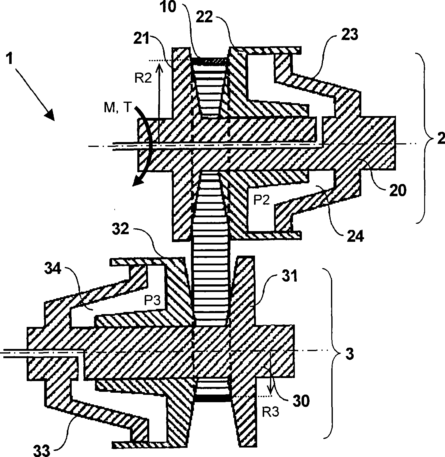
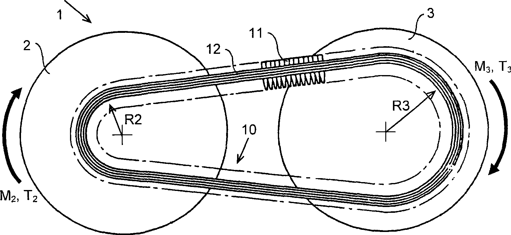
[0027] figure 1There is shown a cross-sectional view of a central portion of a known continuously variable transmission 1 commonly used in the drive train of an automobile between its engine and driven wheels. exist figure 2 A simplified side view of the transmission 1 is provided in .

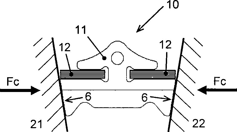
[0028] The known transmission 1 comprises two pulleys 2 and 3, each provided with two pulley sheaves 21, 22 and 31, 32 respectively, between which a drive belt 10 is mounted for running from the drive pulley 2 to the The driven pulley 3 transmits the rotational movement M and the associated torque T. The pulley sheaves 21, 22, 31 and 32 are generally conical in shape and at least one pulley sheave 22, 32 of each pulley 2, 3 is contained in a transmission arranged along its The respective pulley shafts 20, 30 of the respective moving sheaves 22, 32 move axially. In at least the illustrated embodiment, the respective other sheave 21 , 31 of each pulley 2 , 3 is fixed immovably to eg an inte...


PUM


Abstract

The invention provide for a test method for determining the operational lifespan of a pushbelt (10) comprising a multitude of transverse elements (11) that are slideably arranged on one or more endless tensile means (12), wherein the belt (10) is mounted around a driving pulley (2; 61) and a driven pulley (3; 62) while in frictional contact with the respective conical pulley sheaves (21, 22; 31, 32) thereof, wherein the tensile means (12) is tensioned by radially outwardly oriented forces exerted on the transverse metal elements (11) by the pulleys (2, 3; 61, 62) and wherein the belt (10) and pulleys (2, 3; 61, 62) are rotated by applying an input torque (T2) to the driving pulley (2; 61). According to the invention the radially outwardly oriented forces thereby exceed what is minimally required for the belt (10) to be able to transmit the said input torque (T2).

Description

technical field [0001] The present invention relates to a testing method for push tapes, in particular for monitoring the push tape manufacturing process, wherein the quality of the final product push tape is tested by means of a functional lifetime test or a representative life cycle test determining randomly sampled samples. Background technique [0002] Such a push belt is generally known from e.g. European patent application EP-A 1 089 013 and is used primarily as a means for power transmission between two adjustable pulleys of the well known continuously variable transmissions mainly used in automobiles . Known push belts comprise a multitude of relatively thin transverse metal elements slidably contained on one or more endless tensioning devices each comprising at least one flat metal ring. However, annular stretching devices usually comprise a two-layer set of a plurality of such rings radially nested in one another. Push belt ring components are usually made of mar...

Claims


Application Information

Patent Timeline
IPC IPC(8): G01M13/02
CPCG01M13/023
Inventor M-D·特兰J·M·范德文尼P·J·范克罗姆瓦尔特T·E·范欣克尔B·彭宁斯A·布兰德斯玛
Owner ROBERT BOSCH GMBH
Why Eureka
Try Eureka