IPM rotor, IPM rotor manufacturing method and IPM rotor manufacturing apparatus
一种转子、转角部的技术,应用在制造该IPM转子的装置领域,能够解决没有完全填充满树脂、降低IPM转子、树脂低流动性等问题,达到改善NV特性的效果
- Summary
- Abstract
- Description
- Claims
- Application Information
AI Technical Summary
Problems solved by technology
Method used
Image
Examples
Embodiment 1
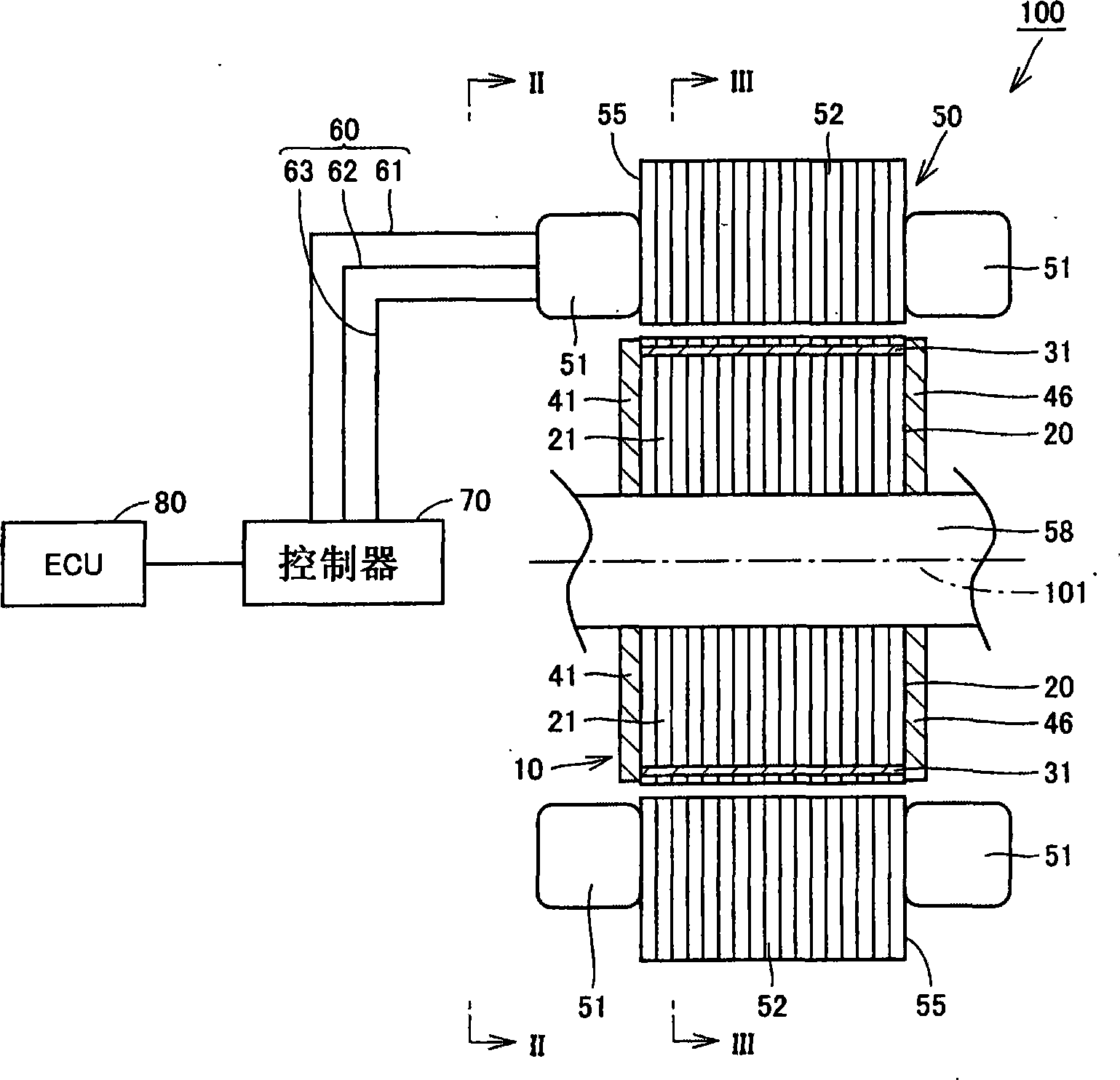
[0036] FIG. 1 is a cross-sectional view schematically showing an electric motor installed in a hybrid vehicle. A hybrid vehicle mounted with an electric motor shown in the figure uses an internal combustion engine such as a gasoline engine or a diesel engine and a rechargeable secondary battery (battery) as a power source.
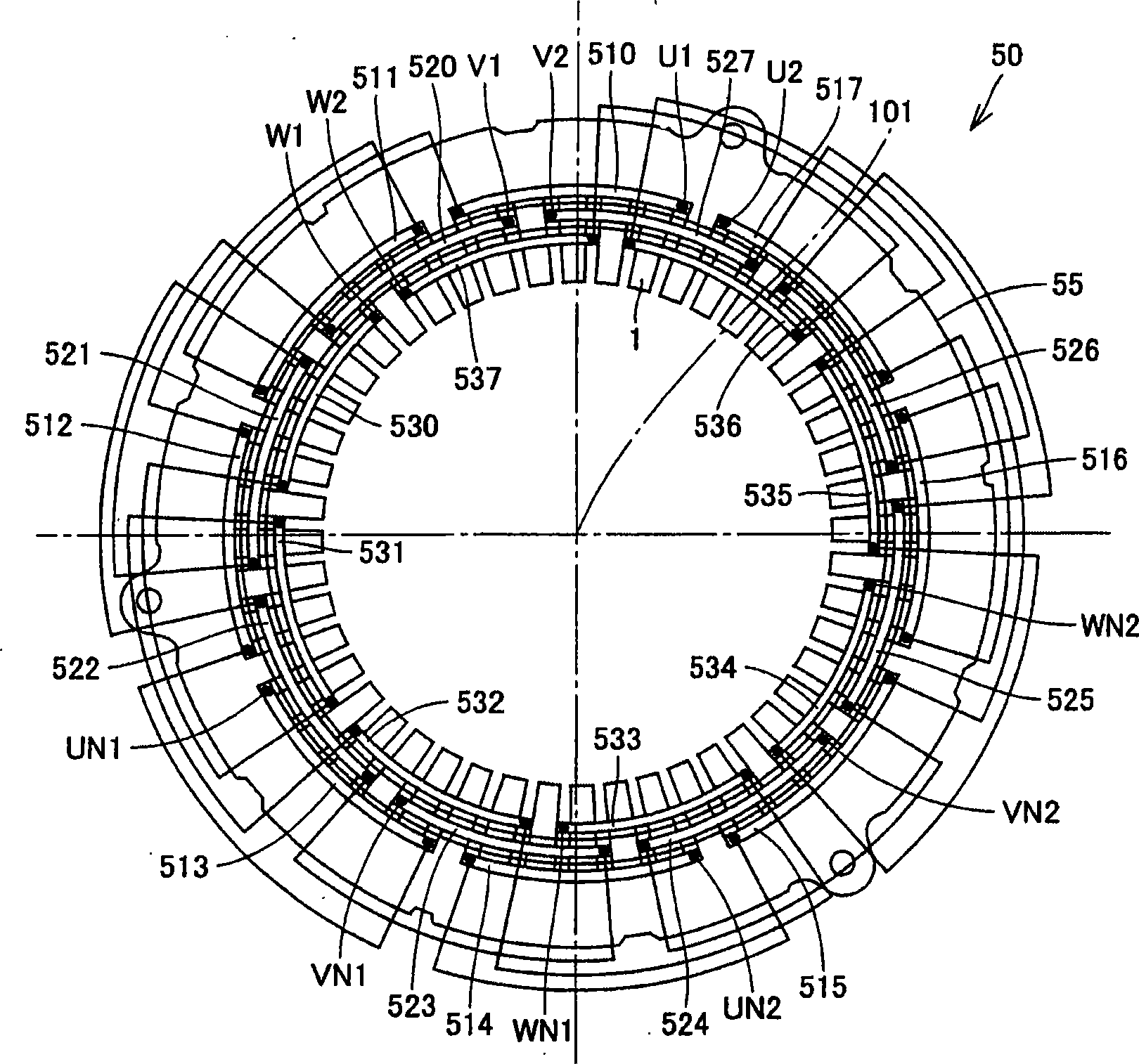
[0037] Referring to FIG. 1 , a motor 100 includes an IPM rotor 10 and a stator 50 disposed on an outer circumference of the IPM rotor 10 . The IPM rotor 10 is disposed on a shaft 58 extending along a central axis 101 . Shaft 58 and IPM rotor 10 rotate together about central axis 101 .
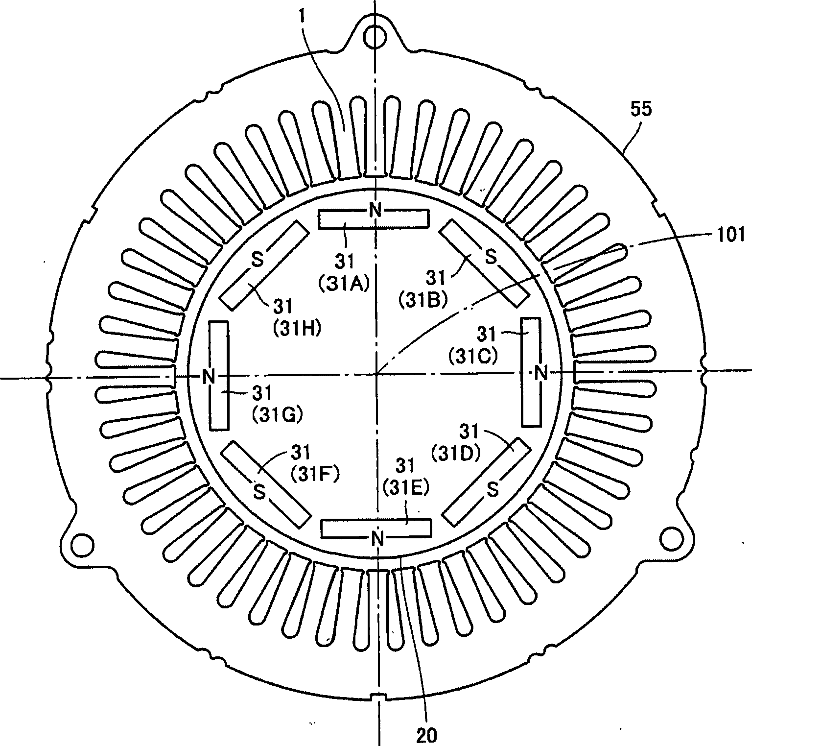
[0038] The IPM rotor 10 includes a rotor core 20 , a permanent magnet 31 embedded in the rotor core 20 , and an unillustrated holding member for holding the permanent magnet 31 on the rotor core 20 . The rotor core 20 has a cylindrical shape extending along the central axis 101 . The rotor core 20 includes a plurality of magnetic steel sheets stacked in the axial directi...
Embodiment 2
[0081] Fig. 14 is an end view of an IPM rotor according to Embodiment 2 of the present invention. FIG. 14 corresponds to FIG. 5 of Embodiment 1. FIG. The IPM rotor 10 of the present embodiment is manufactured using the injection device 200 and the method of manufacturing the IPM rotor 10 according to Embodiment 1. Referring to FIG.
[0082] Referring to FIG. 14, in the present embodiment, the holding member 26 includes a plurality of injection marks 26g. A plurality of injection marks 26g are formed as a thin film on the end surface 20a. A plurality of injection marks 26g are formed continuously from the holding member 26 filling the inner peripheral portion 25p and the outer peripheral portion 25q. A plurality of injection marks 26g are formed at positions overlapping the gates 230m and 230n of FIG. 10 . In the steps shown in FIGS. 9 and 10 of Example 1, the plurality of injection marks 26g are marks for injecting the filler 27 into the gap 25 through the gates 230m and 23...
Embodiment 3
[0085] 15 and 16 are perspective views illustrating steps of manufacturing an IPM rotor according to Embodiment 3 of the present invention. The method of manufacturing an IPM rotor according to this embodiment includes steps similar to those of the method of manufacturing an IPM rotor of Embodiment 1. The overlapping steps will not be described repeatedly below.
[0086] Referring to FIG. 15, in this embodiment, a plurality of fillers 300 are placed on the end face 20a. The positions where the filler 300 is placed are not limited to the positions shown in FIG. 15 , and these positions may be the positions shown in FIGS. 11 and 12 of Embodiment 1. Referring to FIG. The filler 300 is formed by curing a resin material that is a raw material of the holding member 26 . The filler 300 includes a gate portion 310 . The gate part 310 is integrally formed with the filler 300 from a resin material. Each of the plurality of fillers 300 is arranged such that each gate portion 310 over...
PUM
 Abstract
Description
Claims
Application Information
 - R&D
- Intellectual Property
- Life Sciences
- Materials
- Tech Scout
- Unparalleled Data Quality
- Higher Quality Content
- 60% Fewer Hallucinations
Browse by: Latest US Patents, China's latest patents, Technical Efficacy Thesaurus, Application Domain, Technology Topic, Popular Technical Reports.
© 2025 PatSnap. All rights reserved.Legal|Privacy policy|Modern Slavery Act Transparency Statement|Sitemap|About US| Contact US: help@patsnap.com


