
Flexible coupling and vehicle motive power transmission apparatus

A power transmission device and coupling technology, which is applied in the direction of elastic couplings, couplings, mechanical equipment, etc., can solve the problems of high design strength and achieve the effect of reducing design strength

Inactive Publication Date: 2012-10-10
TOYOTA JIDOSHA KK
View PDF5 Cites 2 Cited by
  • Summary
  • Abstract
  • Description
  • Claims
  • Application Information

AI Technical Summary

Problems solved by technology

However, since the absolute value of the maximum value of the torque transmitted by the flexible coupling in the vehicle power transmission device is much larger for positive torque than for negative torque, in the related art negative torque The transfer line is designed to be stronger than required

Method used


Image

  • Flexible coupling and vehicle motive power transmission apparatus
  • Flexible coupling and vehicle motive power transmission apparatus
  • Flexible coupling and vehicle motive power transmission apparatus

Examples


Embodiment Construction

[0040] A flexible coupling and a vehicle power transmission device according to an embodiment of the present invention will be described with reference to the accompanying drawings.

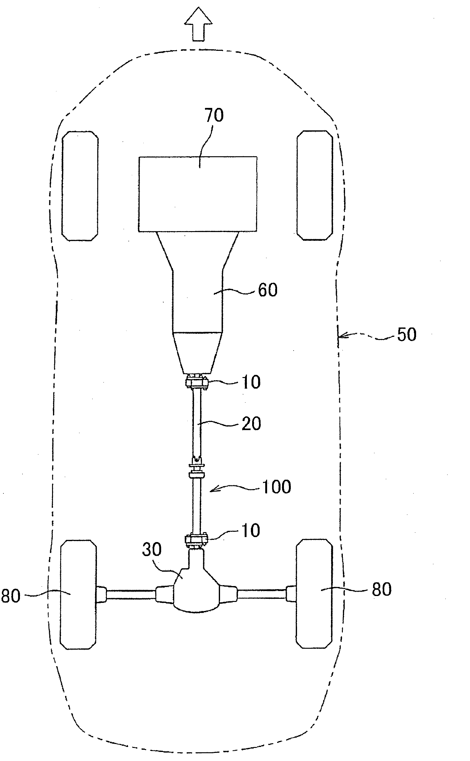
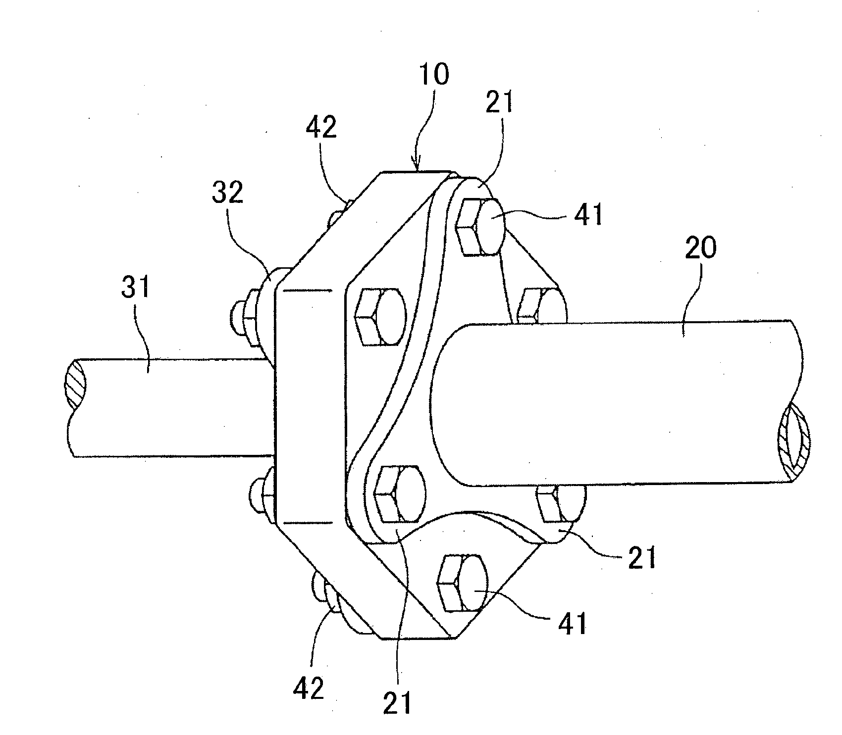
[0041] figure 1 is a plan view of an FR (Front Engine, Rear Wheel Drive) type motor vehicle 50 , showing an engine (drive source) 70 , a transmission 60 , a propeller shaft 20 , a differential gear unit 30 , drive wheels 80 , and the like. The propeller shaft 20 is connected to the output shaft of the transmission 60 and the input shaft of the differential gear unit 30 via the flexible coupling 10 so as to rotate integrally with the output shaft and the input shaft.

[0042] Incidentally, the power transmission device (vehicle power transmission device) 100 that transmits the power of the engine 70 to the drive wheels 80 is composed of the transmission 60 , the front side flexible coupling 10 , the drive shaft 20. Rear side flexible coupling 10, differential gear unit 30 and other components.

...


PUM


Abstract

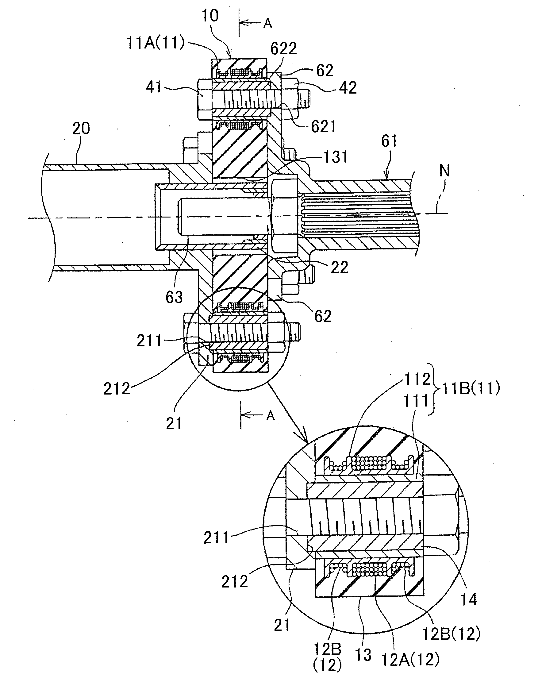
A flexible coupling (10) includes: spool members (11) disposed equidistantly on a circumference; torque transmission lines (12) disposed around adjacent pairs of the spool members (11); and an annular elastic body (13) in which the spool members (11) and the torque transmission lines (12) are embedded. The torque transmission lines (12) consist of first torque transmission lines (12A), and second torque transmission lines (12B) whose total sum of cross-sectional area is a half of that of the first torque transmission lines (12A).; The flexible coupling (10) is constructed so that the first torque transmission lines (12A) transmit positive torque and the second torque transmission lines (12B) transmit negative torque, and is incorporated into a vehicle motive power transmission apparatus that has a hypoid gear whose mesh transmission error is greater during transmission of negative torque than during transmission of positive torque.

Description

technical field [0001] The present invention relates to a flexible coupling that connects rotating shafts to transmit torque and absorb vibration and deflection, and a vehicle power transmission device having the flexible coupling. Background technique [0002] Flexible couplings are sometimes used to connect rotating shafts of vehicles such as propeller shafts and the like (see, for example, Japanese Patent Application Publication No. 2003-28189 (JP-A-2003-28189)). [0003] Such a flexible coupling is composed of the following parts: a wire winding part (referred to as a "bobbin" in Japanese Patent Application Publication No. 2003-28189 (JP-A-2003-28189)), said wire winding part, etc. Arranged at intervals on the circumference around the axis of rotation as the center; torque transmission lines (referred to as "link belts" in Japanese Patent Application Publication No. 2003-28189 (JP-A-2003-28189)), the a torque transmission wire is wound in a loop on every two wire windin...

Claims


Application Information

Patent Timeline
Patent Type & Authority Applications(China)
IPC IPC(8): F16D3/68F16D3/78
CPCF16D3/78F16D3/62
Inventor 阿部隆行
Owner TOYOTA JIDOSHA KK
Learn More