Speaker
A loudspeaker and piezoelectric vibration technology, applied in the direction of sensors, sensor types, piezoelectric/electrostrictive transducers, etc., can solve the problem of piezoelectric vibration plate bending, no longer play speakers, piezoelectric vibration plate amplitude limit, etc. problem, to achieve the effect of reproducing the sound pressure
- Summary
- Abstract
- Description
- Claims
- Application Information
AI Technical Summary
Problems solved by technology
Method used
Image
Examples
Embodiment approach 1
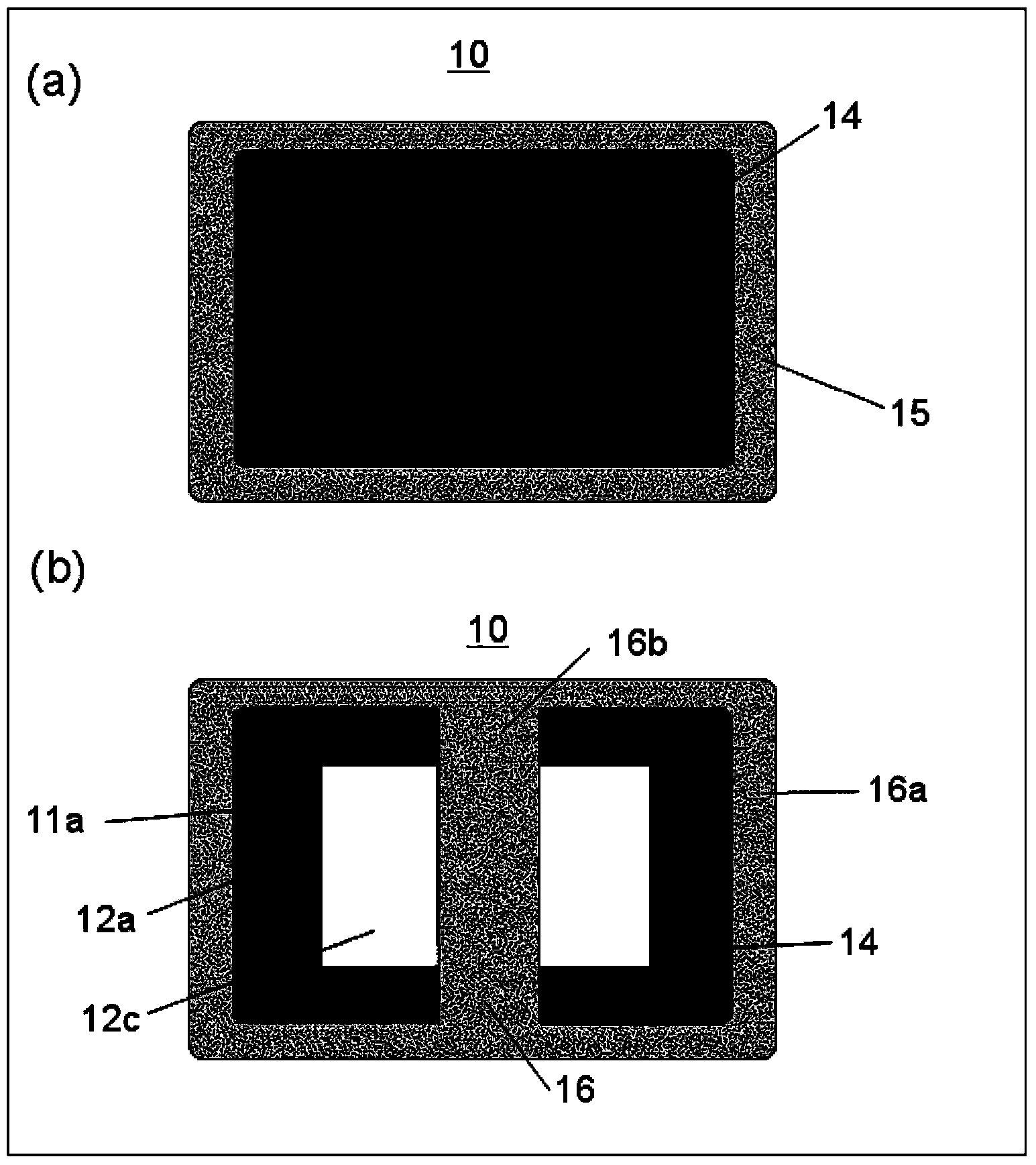
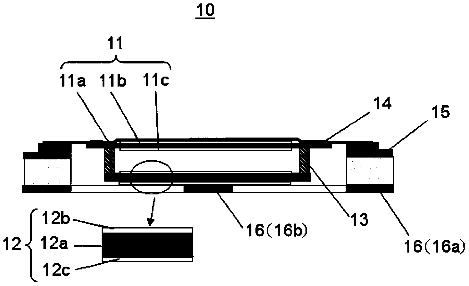
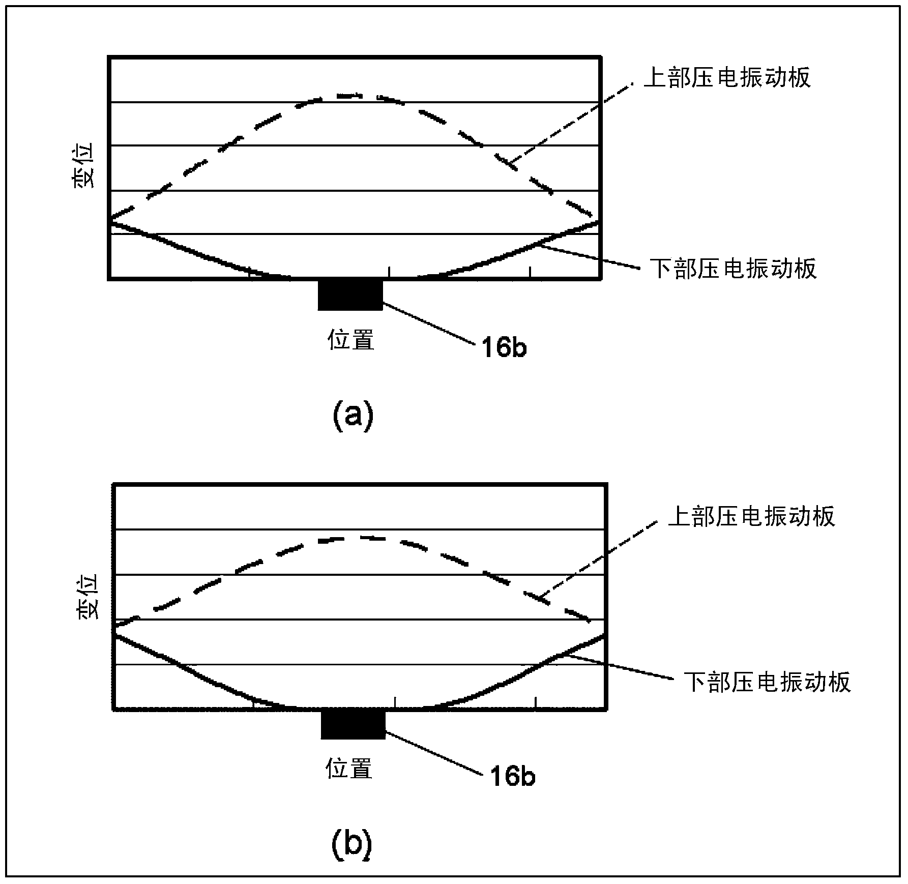
[0045] The piezoelectric speaker according to Embodiment 1 of the present invention includes two piezoelectric diaphragms having different rigidities, a connecting member connecting the two piezoelectric diaphragms, and a piezoelectric speaker on the sound emission surface side. In the case of the upper side of the speaker, the frame supports the central portion of the piezoelectric diaphragm located on the lower side. In addition, by using a more rigid vibration plate for the piezoelectric vibration plate having a larger maximum value of the bending stress acting at the amplitude of the two piezoelectric vibration plates, the vibration of each piezoelectric vibration plate at a large amplitude is controlled. attitude, so that the maximum value of the stress can be reduced, and the maximum sound pressure that can be reproduced can be increased.
[0046] figure 1 is a front view of the piezoelectric speaker 10 according to Embodiment 1 ( figure 1 (a)) and rear view ( figu...
Embodiment approach 2
[0066] The piezoelectric speaker 20 according to Embodiment 2 includes two piezoelectric diaphragms having different rigidities, a connecting member connecting the two piezoelectric diaphragms, and a structure for supporting the piezoelectric diaphragm on the lower side (back side). end frame. In addition, by using a vibration plate with a higher rigidity for the piezoelectric vibration plate having a larger maximum value of the bending stress acting on vibration among the two piezoelectric vibration plates, the vibration of each piezoelectric vibration plate at a large amplitude is controlled. The vibration posture can reduce the maximum value of stress and increase the maximum sound pressure that can be reproduced.
[0067] Figure 6 It is a sectional view of the piezoelectric speaker 20 according to the second embodiment.
[0068] Such as Figure 6 As shown, piezoelectric speaker 20 includes upper piezoelectric diaphragm 21 (front side diaphragm), lower piezoelectric dia...
Embodiment approach 3
[0081] The piezoelectric speakers 30 and 40 according to Embodiment 3 are different from the above-described embodiments in that they have three piezoelectric diaphragms. Figure 8A It is a sectional view of the piezoelectric speaker 30 according to the third embodiment. Figure 8B is related to Embodiment 3 and Figure 8A Cross-sectional views of piezoelectric speakers 40 in different forms.
[0082] Piezoelectric speaker 30 such as Figure 8A As shown, three piezoelectric vibration plates 31 , 32 , and 33 , a plurality of connection members 37 a , 37 b , and 38 , an edge 34 , an upper frame 35 , and a lower frame 36 are provided. Each of the piezoelectric vibrating plates 31 , 32 , and 33 is a vibrating plate having a bimorph structure. In each piezoelectric vibrating plate 31 , 32 , 33 , piezoelectric elements 31 b , 31 c , 32 b , 32 c , 33 b , 33 c are bonded to both surfaces of base materials 31 a , 32 a , 33 a , respectively. In addition, from the front side of the s...
PUM
 Abstract
Description
Claims
Application Information
 - R&D
- Intellectual Property
- Life Sciences
- Materials
- Tech Scout
- Unparalleled Data Quality
- Higher Quality Content
- 60% Fewer Hallucinations
Browse by: Latest US Patents, China's latest patents, Technical Efficacy Thesaurus, Application Domain, Technology Topic, Popular Technical Reports.
© 2025 PatSnap. All rights reserved.Legal|Privacy policy|Modern Slavery Act Transparency Statement|Sitemap|About US| Contact US: help@patsnap.com


