A controllable preparation method of photoresponsive surface wrinkle microstructure
A photoresponse, microstructure technology, applied in optomechanical equipment, photoengraving process of pattern surface, photosensitive material for optomechanical equipment, etc. Effect
- Summary
- Abstract
- Description
- Claims
- Application Information
AI Technical Summary
Problems solved by technology
Method used
Image
Examples
Embodiment 1
[0022] A controllable preparation method of a photoresponsive surface wrinkle microstructure, comprising the following steps:
[0023] Step 1. Mix the PDMS prepolymer and crosslinking agent Sylgard184 (purchased from Dow Corning, USA) at a mass ratio of 10:1, and fully stir with a glass rod to form a uniform prepolymer; After degassing in a multi-purpose vacuum pump for 1 hour, pour it into a watch glass; heat at 70°C for 4 hours to cure; obtain a PDMS soft substrate;
[0024] Step 2, carry out oxygen plasma surface activation treatment to the PDMS soft substrate obtained in step 1, then spin-coat a chloroform solution of 1wt% polymethyl methacrylate (PMMA) (spin-coating parameters: 4000rpm, 60s), and degas in a vacuum pump Remove residual organic solvent to obtain PDMS / PMMA soft and hard composite system.
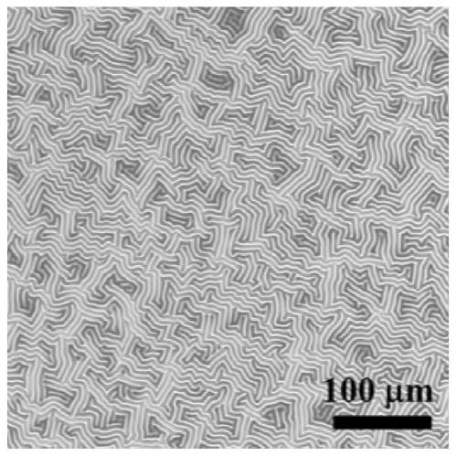
[0025] Step 3: Heat the PDMS / PMMA composite system obtained in Step 2 at 100°C for 1 hour, and cool to room temperature with the furnace to obtain a maze-like surface wri...
Embodiment 2
[0030] A controllable preparation method of a light-responsive surface wrinkle microstructure, the preparation process of which is basically the same as that of Example 1, the only difference being:
[0031] In step 2, the degradable polymer is changed from PMMA to poly-L-lactic acid (PLLA), and the spin coating speed is changed from 4000rpm to 5000rpm to obtain a PDMS / PLLA soft-hard composite system;
[0032] In step 3, the heating temperature was changed from 100°C to 90°C, and the wrinkled pattern on the surface of the PDMS / PLLA soft-hard composite system was as follows: Figure 4 As shown in the light microscope diagram;
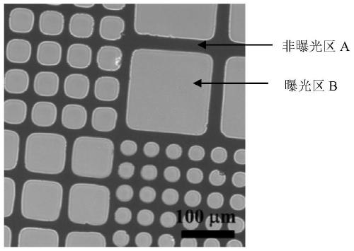
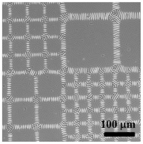
[0033] In step 4, the stamped photomask is made of figure 2 The photomask 1 shown is changed as Figure 5 Photomask 2 shown, light dose from 0-13.2J cm -2 Change to 0-19.2J cm -2 , so as to control the amplitude of the wrinkle topography in the exposed area A (measured by atomic force microscope), as shown in Table 2; at the same time, the wrinkles ...
PUM
 Abstract
Description
Claims
Application Information
 - R&D
- Intellectual Property
- Life Sciences
- Materials
- Tech Scout
- Unparalleled Data Quality
- Higher Quality Content
- 60% Fewer Hallucinations
Browse by: Latest US Patents, China's latest patents, Technical Efficacy Thesaurus, Application Domain, Technology Topic, Popular Technical Reports.
© 2025 PatSnap. All rights reserved.Legal|Privacy policy|Modern Slavery Act Transparency Statement|Sitemap|About US| Contact US: help@patsnap.com


