

Relational model of driver fatigue and vehicle riding trail
A driving fatigue and driver technology, applied in medical science, sensors, diagnostic recording/measurement, etc., can solve the problems of no quantitative analysis method, lack of driving fatigue warning rules, etc.
Inactive Publication Date: 2009-07-29
BEIJING INSTITUTE OF TECHNOLOGYGY
View PDF0 Cites 21 Cited by
- Summary
- Abstract
- Description
- Claims
- Application Information
AI Technical Summary
Problems solved by technology
But so far there is no recognized quantitative analysis method, and there is even a lack of driving fatigue warning rules based on vehicle driving trajectories.
Method used
View moreImage
Smart ImageViewing Examples

Examples
Embodiment Construction
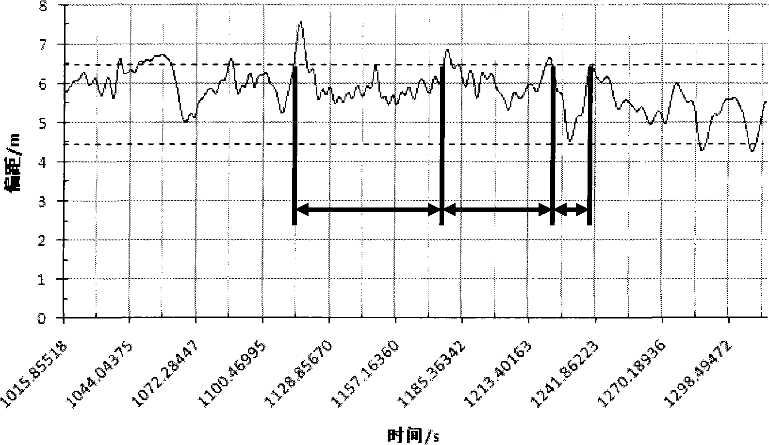
[0029] Using the lane line recognition technology to extract the lane marking line or road boundary information in the road to calculate the lane line offset and crossing the lane line, the invention can be used to establish a driving fatigue recognition and early warning system based on the vehicle driving track.
Login to View More PUM
 Abstract
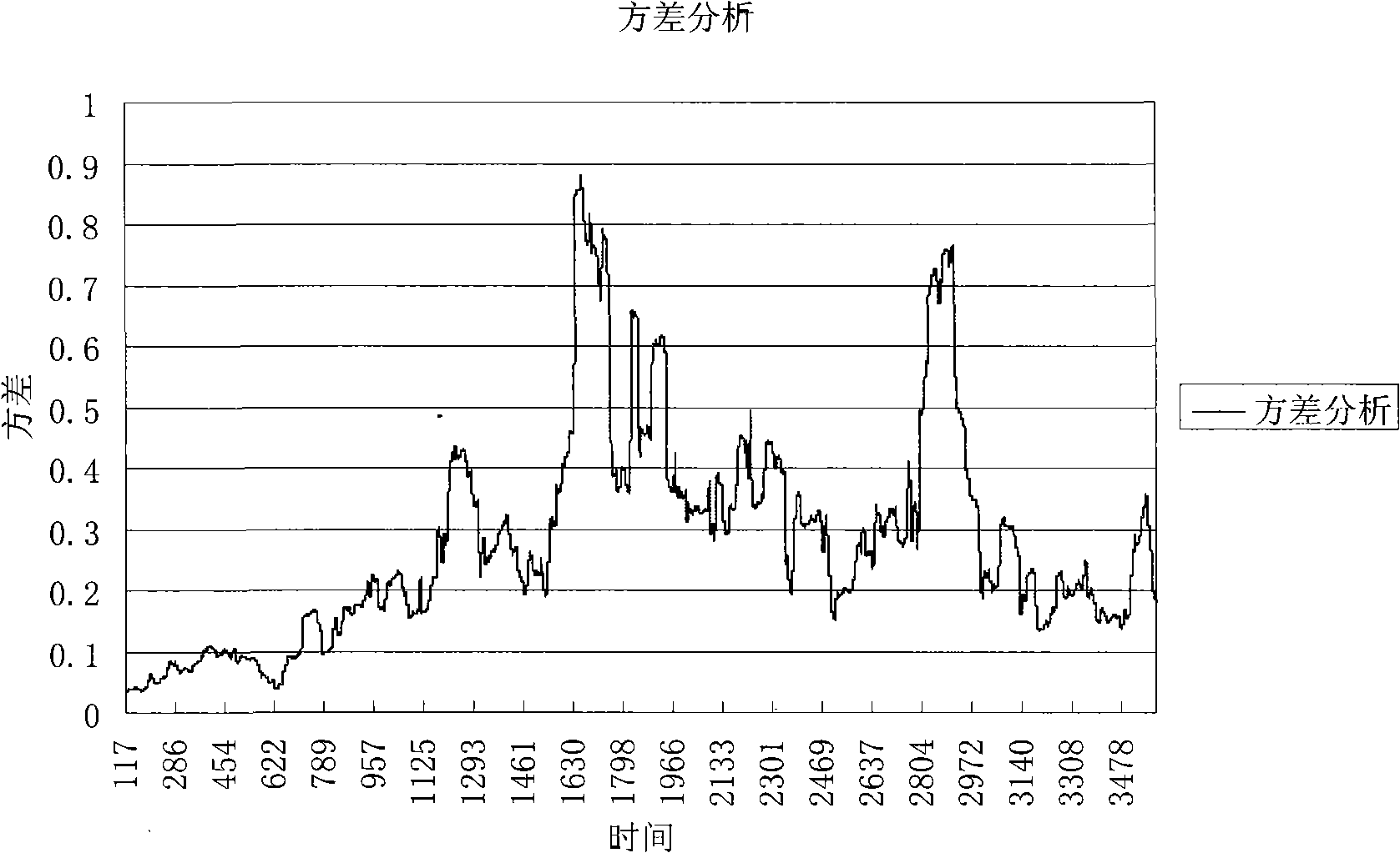
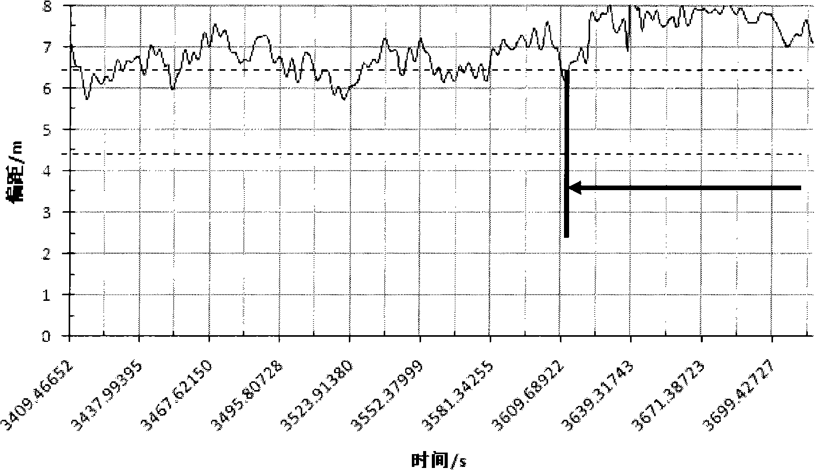
The invention relates to a relation model between driver fatigue and vehicle driving track, and belongs to the field of transportation. Aiming at fatigue driving early warning application background, by simulating a driving fatigue sampling test of a human-vehicle-road (environment) system in a constructed semi-physical virtual traffic environment, adopting percentage of delta waves and theta waves in facial expression and brain waves of a driver as a standard for judging fatigue degree of the driver, and adopting a method combining time domain analysis and mathematical statistics analysis, the invention researches and determines periodic decreasing driving fatigue preliminary early warning rules of the track of a right front wheel of a vehicle from a right lane line and driving fatigue judgment limit of offset variance of the lane line, can judge fatigue characteristics or moderate fatigue state of the driver, and also researches and determines serious fatigue driving warning rules of abnormal vehicle lane changing. A driving fatigue recognition and early warning system based on the vehicle running track can be established by the invention.
Description
technical field [0001] The invention belongs to the field of traffic and transportation. Aiming at the application background of fatigue driving early warning, it finds the relationship between vehicle driving trajectory and driving fatigue degree through experiments, and provides quantitative basis for further establishing driving fatigue recognition and early warning based on vehicle driving trajectory, and provides traffic safety management. system solutions. Background technique [0002] With the rapid increase of vehicle ownership, the number of traffic accidents remains high, especially in low- and middle-income countries. Traffic safety has attracted the attention of governments and societies around the world. Studies have shown that traffic safety is affected by many factors. Experts at home and abroad have concluded through statistics and research that about 80% of traffic accidents are caused by human factors, and most road traffic accidents are caused by people (m...
Claims
Login to View More Application Information
Patent Timeline
 IPC IPC(8): A61B5/18
Inventor高利吕超吴绍斌赵亚男王刘安陈雪梅孙洪武
OwnerBEIJING INSTITUTE OF TECHNOLOGYGY