
Descending device for saving life

A technology of landing device and pincer tip, applied in the field of life-saving landing device, can solve the problem of the above crowd being unable to escape, and achieve the effect of promoting completeness

Inactive Publication Date: 2009-08-05
陈烈彬
View PDF0 Cites 6 Cited by
  • Summary
  • Abstract
  • Description
  • Claims
  • Application Information

AI Technical Summary

Problems solved by technology

[0002] In the past, the building design did not exceed 10 floors, and the fire-fighting facilities could keep up. Although there are safety door passages designed for floors above 10 to 30 floors, once the fire seals the elevator and the safety passage, the people above cannot escape.

Method used


Image

  • Descending device for saving life

Examples


Embodiment Construction

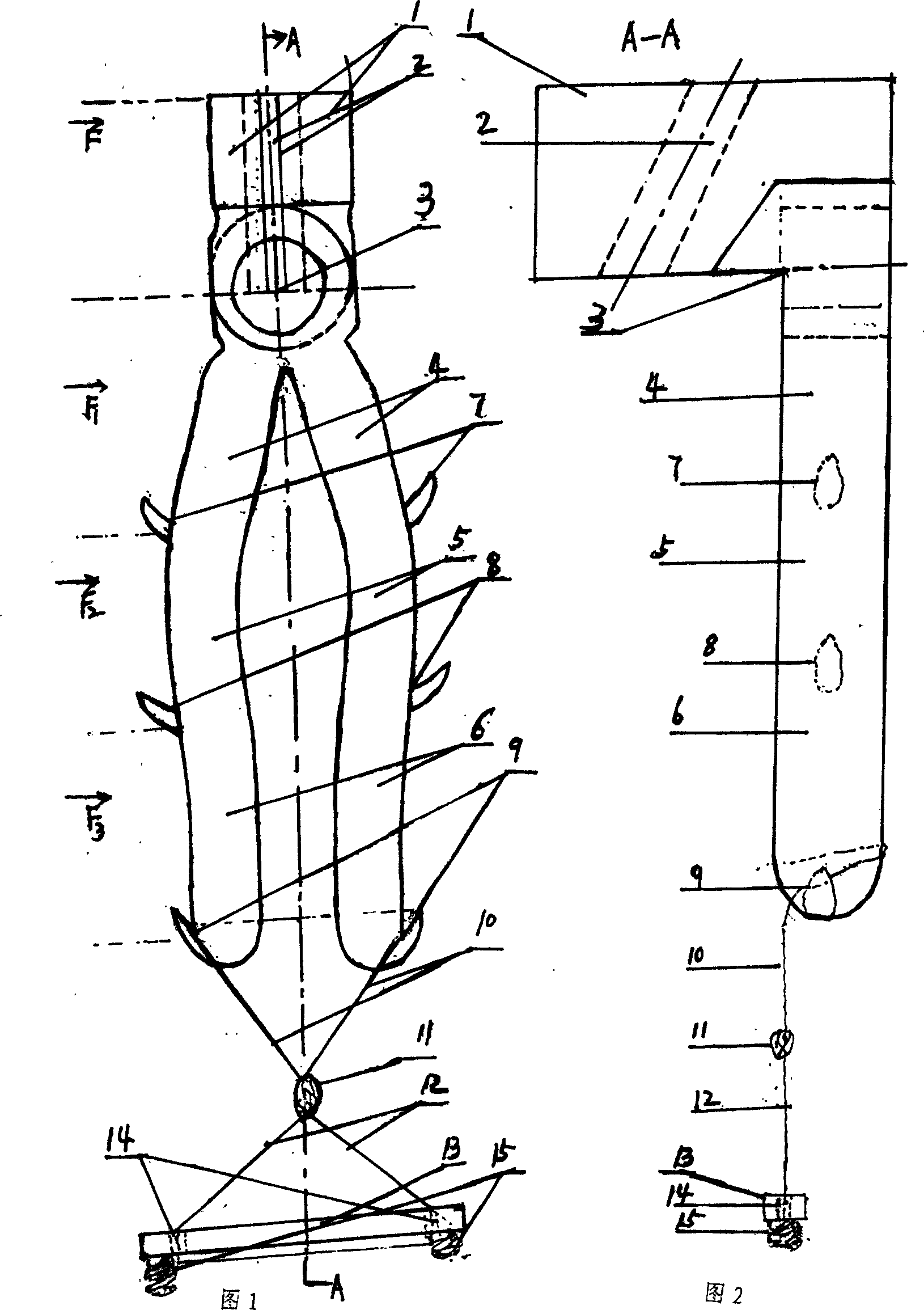
[0011] A life-saving descender of the present invention, taking the production of a 10-inch life-saving descender as an example, it is necessary to make two sets of pliers arms corresponding to the front and back of the mold, drill holes at the fulcrums, and rivet the fulcrums, so that the two pliers arms can be used flexibly , Chi fire. The 8-shaped upper and lower buckle rings are made of flame-retardant material ropes, the seat board can be made of wood or bamboo boards, and the shock-absorbing spring can bear 30-50kg.


PUM


Abstract

The invention discloses a life-saving landing apparatus, and relates to the technical field of architectural design and firefighting facilities. The life-saving landing apparatus is mainly and technically characterized in that the point of a pair of pliers is bent into 90 DEG, and the handle of the pliers is three times longer than the point of the pliers; B-shaped upper buckle collars are hung on double hooks; and after the weight of a person is loaded, a semicircular hole of the point of the pliers clamps a multistrand rope, and the escape person holds the handle of the pliers tightly or loosely by two hands to control the slip velocity of the life-saving landing apparatus so as to land safely. The invention provides a life-saving landing apparatus which has the advantages of safe escape and convenient use.

Description

Technical field [0001] The invention relates to a life-saving descender, which relates to the technical fields of architectural design and fire-fighting facilities. Background technique [0002] In the past, the building design did not exceed 10 floors, and the fire-fighting facilities could keep up. Although there are safety door passages designed for floors above 10 to 30 floors, once the fire seals the elevator and the safety passage, the people above cannot escape. Contents of the invention [0003] In order to overcome the deficiencies and defects of architectural design and fire-fighting facilities, how to face the sea of ​​fire and quickly rescue the crowd trapped by the sea of ​​fire in the future is the purpose of escaping from the 10th floor to the 30th floor. [0004] The technical solution (Fig. 1) adopted by the present invention to solve the technical problem is: the tip of the pliers (1) bends 90° to connect the oblique semicircular hole (2), (2) connects th...

Claims


Application Information

Patent Timeline
IPC IPC(8): A62B1/06A62B1/14
Inventor 陈烈彬
Owner 陈烈彬
Learn More