Inducer

A technology of inductors and magnetic cores, applied in the field of inductors, can solve the problems of high effective magnetic permeability, low saturation resistance, large magnetic flux, etc.

Inactive Publication Date: 2009-08-05
SHENZHEN ZHENHUA FU ELECTRONICS
View PDF0 Cites 2 Cited by
  • Summary
  • Abstract
  • Description
  • Claims
  • Application Information

AI Technical Summary

Problems solved by technology

[0003] Since the coil is wound on a magnetic column 111, the magnetic induction line is almost along the magnetic core

Method used


Image

  • Inducer
  • Inducer
  • Inducer

Examples


Embodiment Construction

[0014] In order to make the object, technical solution and advantages of the present invention clearer, the present invention will be further described in detail below in conjunction with the accompanying drawings and embodiments. It should be understood that the specific embodiments described here are only used to explain the present invention, not to limit the present invention.

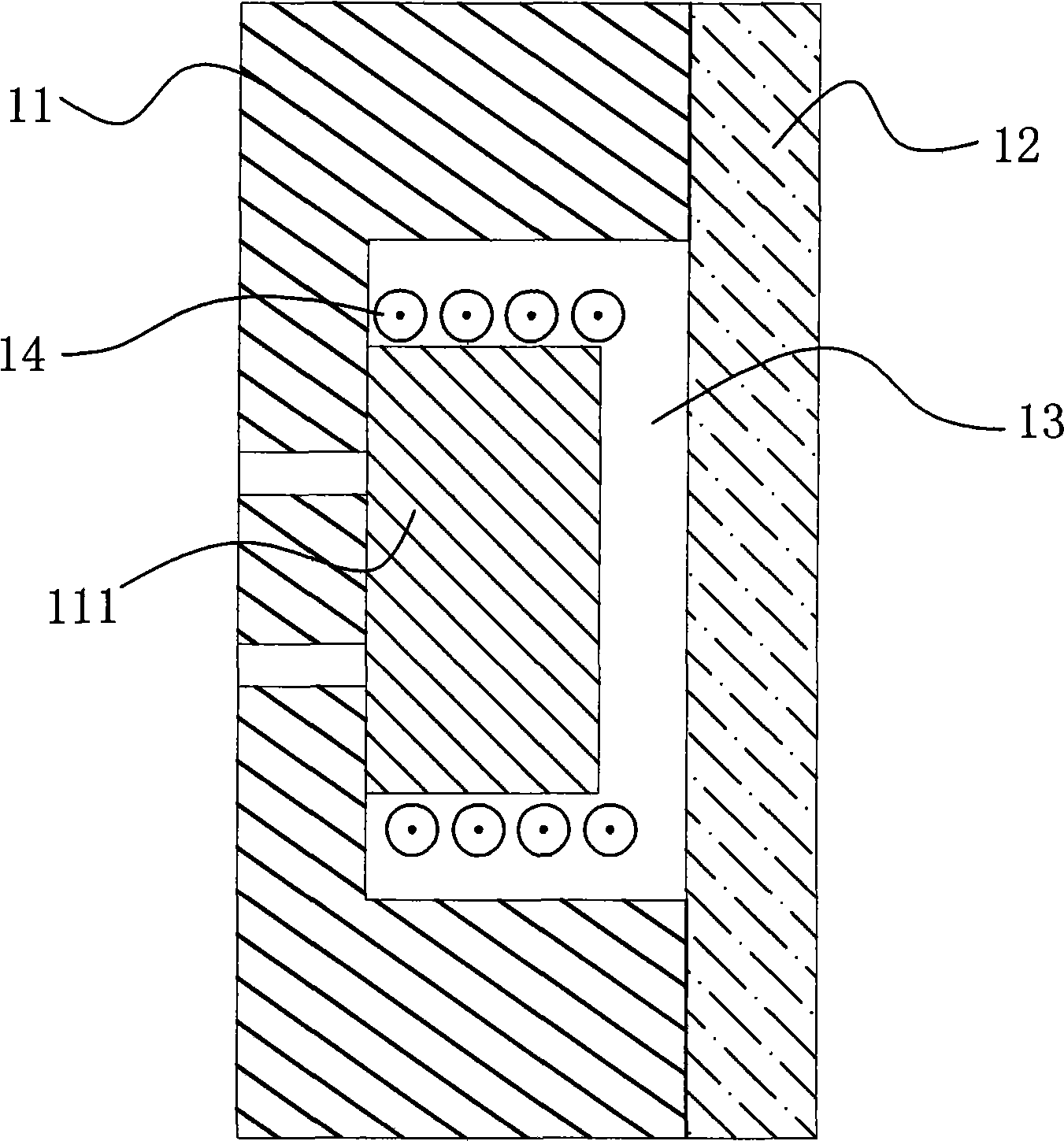
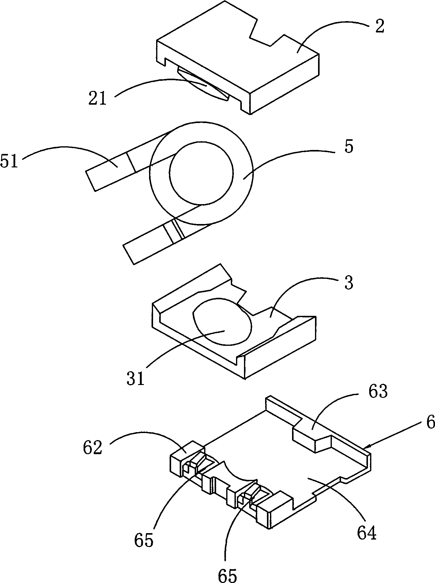
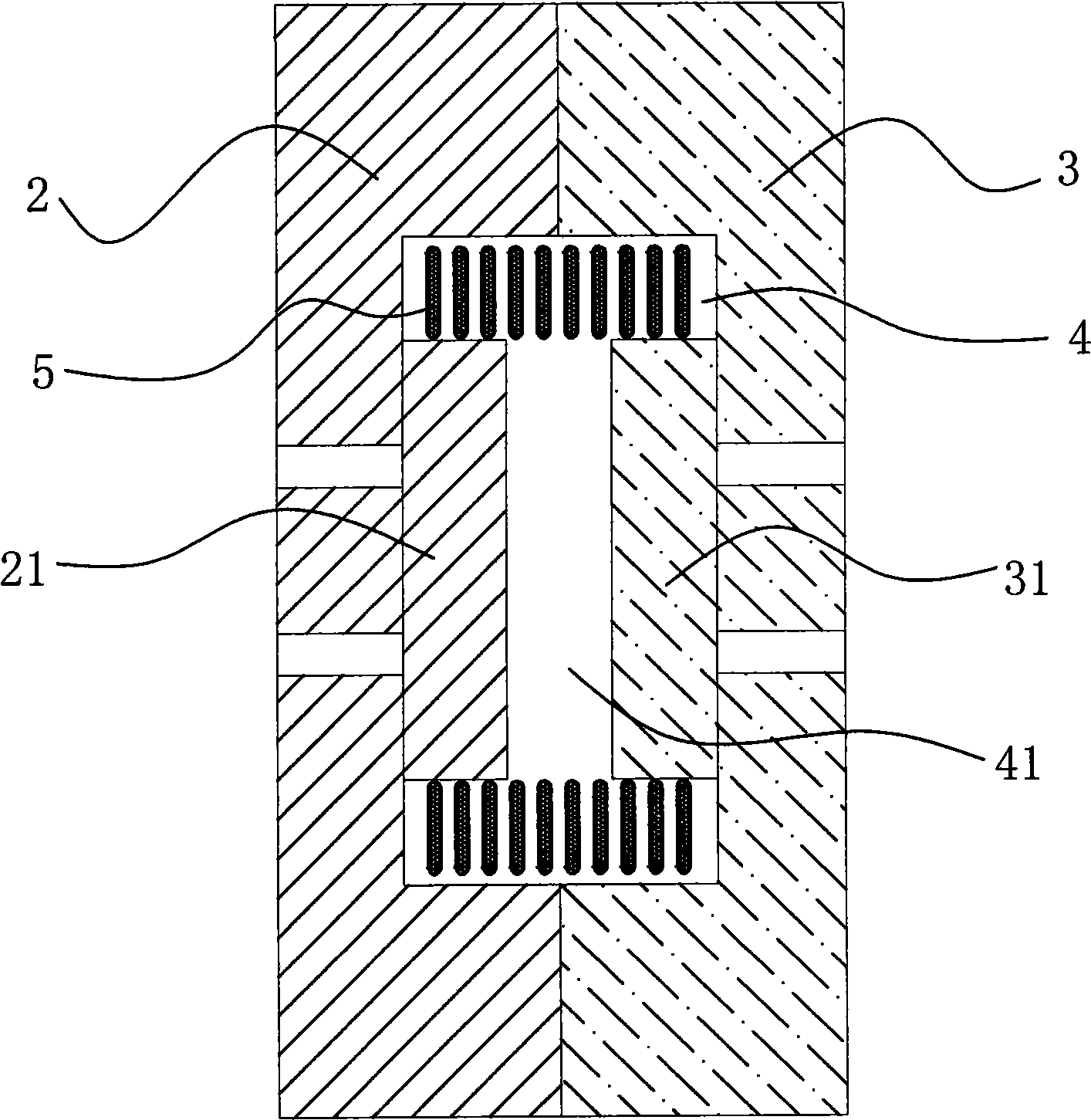
[0015] see figure 1 and figure 2 , the embodiment of the present invention provides an inductor, including a first magnetic core 2 and a second magnetic core 3 , the first magnetic core 2 and the second magnetic core 3 are connected to form a cavity 4 . In the cavity 4 , a first magnetic column 21 is disposed on the first magnetic core 2 , and a second magnetic column 31 coaxial with the first magnetic column 21 is oppositely disposed on the second magnetic core 2 . There is a gap 41 between the end faces of the first and second magnetic columns 21 and 31 , and a coil 5 is wound on the first mag...


PUM

PropertyMeasurementUnit
Dc resistanceaaaaaaaaaa

Abstract

The invention provides an inductor, including a first magnetic core and a second magnetic core; the first magnetic core is connected with the second magnetic core, forming a cavity. In the cavity, the first magnetic core is provided with a first magnetic pillar; the second magnetic core is also correspondingly provided with a second magnetic pillar which is coaxial with the first magnetic pillar; a certain gap is arranged between the end surfaces of the first magnetic pillar and the second magnetic pillar; and a coil is wound on the first magnetic pillar, the gap and the second magnetic pillar. A certain gap is arranged between the first magnetic pillar and the second magnetic pillar. By winding the coil on the two magnetic pillars, after being electrified, the magnetic force lines are centralized around the coil. As the current-carrying coil does not have magnetic pillars at the gap part, the generated magnetic induction lines are dispersed in the whole space; and compared with the prior art in which the coil is wound on the whole magnetic pillar, the technical proposal improves the saturation resistance capacity of the inductor and reduces the permeability.

Description

technical field [0001] The invention belongs to an electronic component, in particular to an inductor. Background technique [0002] An inductor currently on the market, such as figure 1 As shown, it includes a first magnetic core 11 and a second magnetic core 12, the first magnetic core 11 and the second magnetic core 12 are circumferentially sealed and connected to form a cavity 13, and a coil 14 wound with a coil 14 is arranged on the first magnetic core 11 in the cavity 13. The magnetic column 111 has a certain gap between the end surface of the magnetic column 111 and the second magnetic core 12 . [0003] Since the coil is wound on a magnetic column 111, the magnetic induction line is almost along the magnetic core, so that the magnetic flux is large, the effective magnetic permeability is high, and the saturation resistance is low. Contents of the invention [0004] The technical problem to be solved by the present invention is to provide an inductor that can redu...

Claims


Application Information

Patent Timeline
IPC IPC(8): H01F17/04H01F27/24H01F41/00
Inventor 丁晓鸿王上衡肖倩王胜刚滕林於斌樊应县周飞宜曹华春
Owner SHENZHEN ZHENHUA FU ELECTRONICS
Why Eureka
Try Eureka