Rotary type joint of robot
A robot and rotary technology, applied in the direction of manipulators, manufacturing tools, joints, etc., can solve the problems of reducing the realization cost and cost performance, and achieve the effect of easy purchase, low price and large transmission torque
- Summary
- Abstract
- Description
- Claims
- Application Information
AI Technical Summary
Problems solved by technology
Method used
Image

Examples
Embodiment Construction
[0015] Embodiments of the present invention are described in detail below in conjunction with accompanying drawings: the present embodiment is implemented under the premise of the technical solution of the present invention, and detailed implementation methods and specific operating procedures are provided, but the scope of protection of the present invention is not limited to Examples described below.
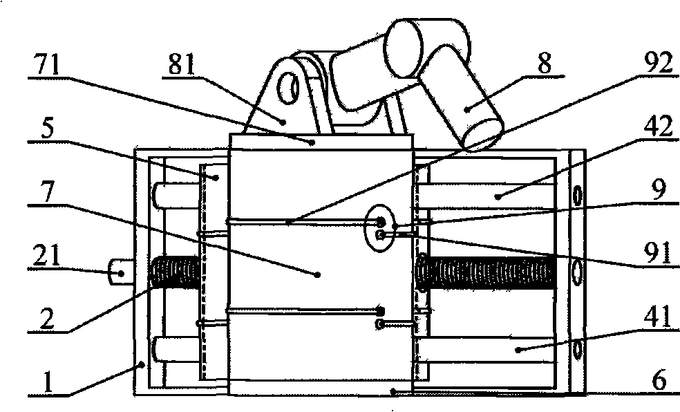
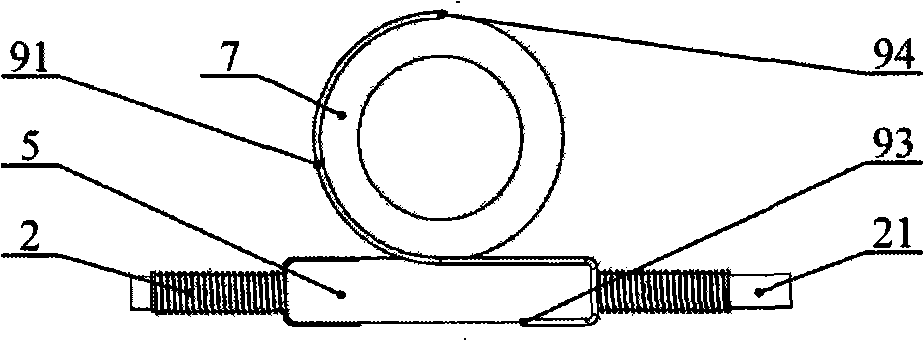
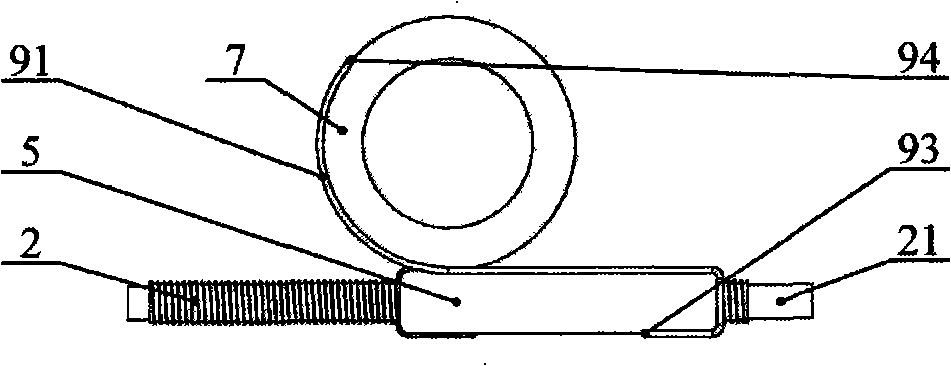
[0016] Such as figure 1 , Figure 4 and Figure 5 As shown, the present embodiment includes: a fixed frame 1, a screw mandrel 2, a nut 3, guide rods 41 and 42, a moving block 5, a waist fixed base 6, a waist turntable 7, and a wire couple 9. The screw rod 2 is installed on the fixed frame 1, and can freely rotate along its own axis relative to the fixed frame 1, and is connected to the joint end 21 of the screw rod 2 by an external driving element for transmission. The nut 3 is fixedly installed on the moving block 5 . Guide rods 41 and 42 are also installed on the fixed f...
PUM
 Abstract
Description
Claims
Application Information
 - R&D
- Intellectual Property
- Life Sciences
- Materials
- Tech Scout
- Unparalleled Data Quality
- Higher Quality Content
- 60% Fewer Hallucinations
Browse by: Latest US Patents, China's latest patents, Technical Efficacy Thesaurus, Application Domain, Technology Topic, Popular Technical Reports.
© 2025 PatSnap. All rights reserved.Legal|Privacy policy|Modern Slavery Act Transparency Statement|Sitemap|About US| Contact US: help@patsnap.com