
Door handle

A door handle and operating handle technology, applied in the field of door handles, can solve the problems of poor appearance, difficult operability, easy to be stained with dust, etc.

Inactive Publication Date: 2009-08-12
TAKIGEN MFG CO LTD
View PDF1 Cites 5 Cited by
  • Summary
  • Abstract
  • Description
  • Claims
  • Application Information

AI Technical Summary

Problems solved by technology

However, in the conventional door handle, since the lock groove of the lock lever is engaged with the lock member of the bracket from the rotational direction by the rotational operation of the operating handle, in order to enable the gasket to be used in a compressed state, When the lock lever is engaged with the bracket, the door must be closed with great force, and the operation handle is rotated while the door is strongly pushed against the fixed frame body, so there is a problem that it is difficult to realize simple operability
In addition, if the door is simply closed by force and pushed against the fixed frame body, it is difficult to compress the gasket reliably due to the elastic recovery of the gasket, so there is a problem that it is difficult to completely seal the door.
And, in the structure where only the lock groove of the lock lever is engaged with the lock member of the bracket from the rotational direction, if the lock member of the bracket is not close to the lock groove of the lock lever, the lock lever cannot be locked. Problems engaging with brackets
In addition, in the case of the conventional door handle, since the bracket is fixed to the fixed frame body with mounting screws, and the fixed base is fixed to the door with mounting screws, the mounting screws are exposed to the outside, so there are poor appearance and The installation position of the mounting screws is prone to dust and difficult to clean

Method used


Image

  • Door handle
  • Door handle
  • Door handle

Examples


Embodiment Construction

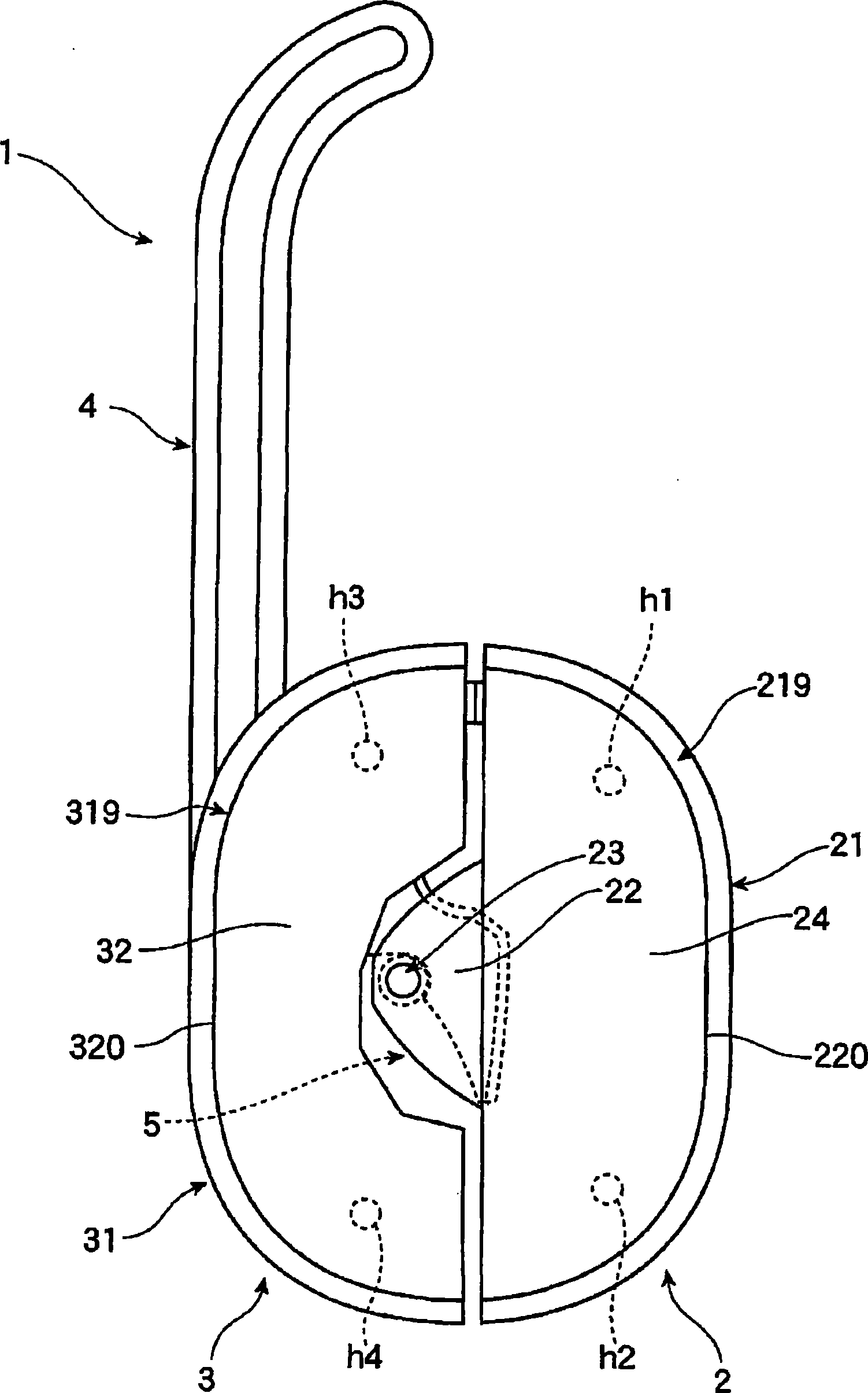
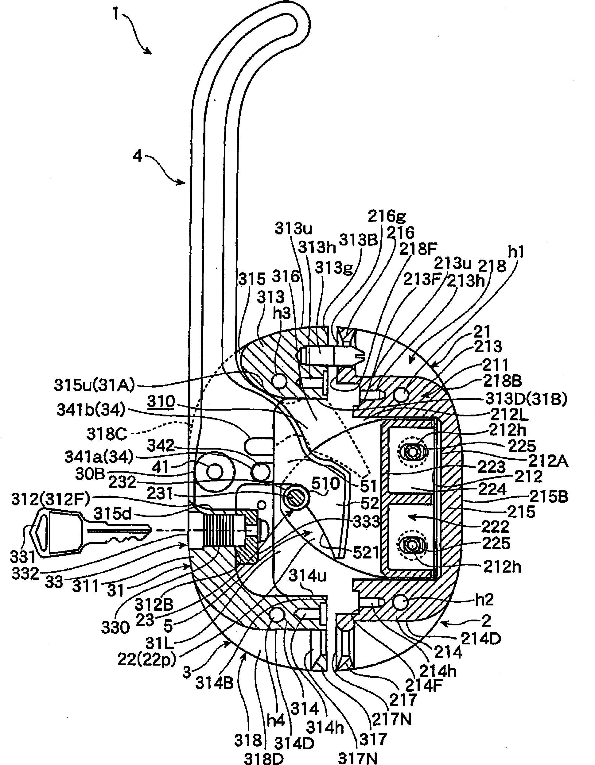
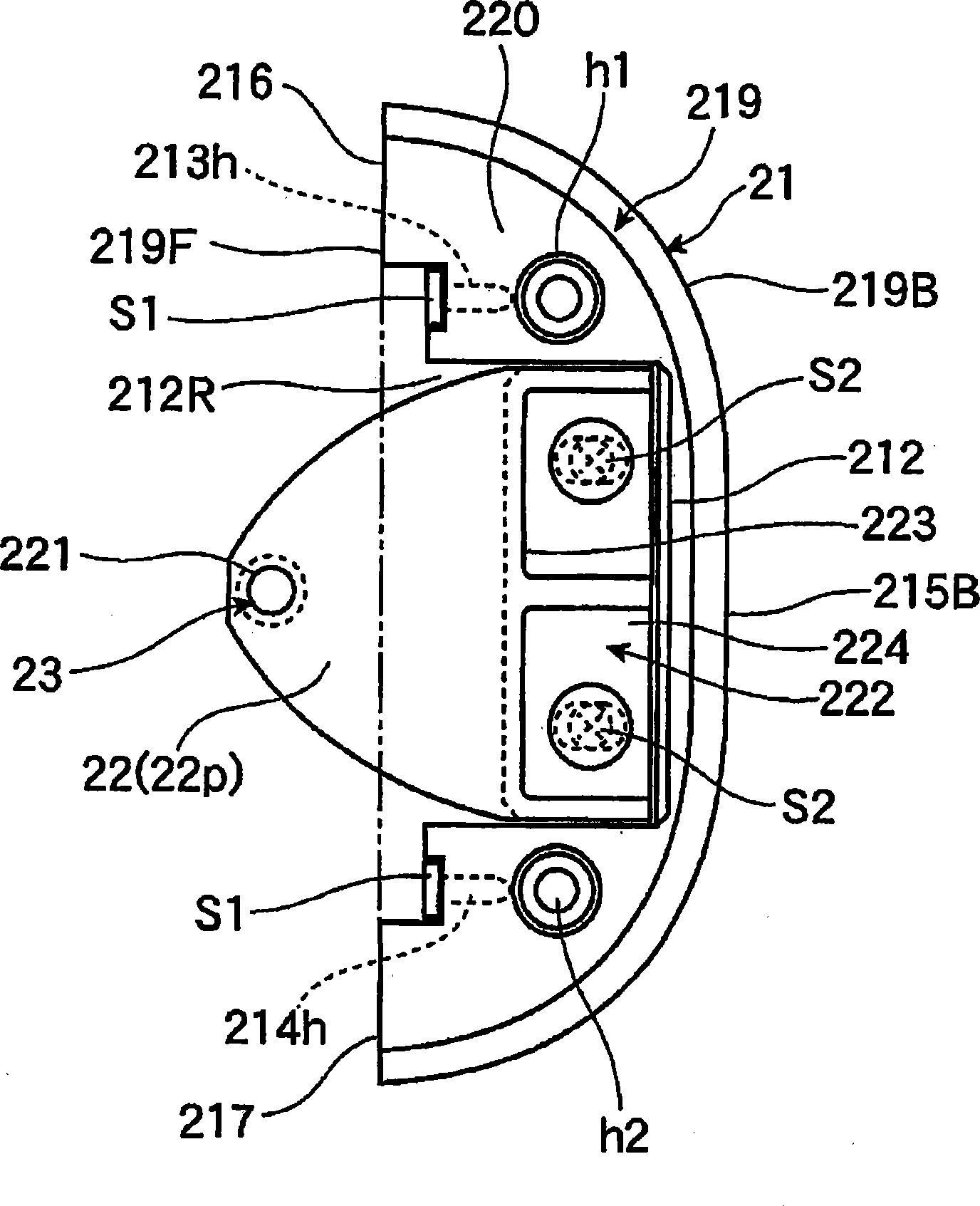
[0135] Hereinafter, an embodiment of the present invention will be described with reference to the accompanying drawings. figure 1 Partially broken side view for the door handle, figure 2 It is a side sectional view of the door handle. image 3 For the right side view of the door handle especially the bracket, Figure 4 is the front view of the bracket. Figure 5 It is the front view of the door handle, especially the fixed base and the operating handle, Image 6 Partially broken back view of the fixed base, the operating handle and the locking lever.

[0136] like figure 1 and figure 2 As shown, the door handle 1 includes a bracket 2 fixedly connected to the fixed frame body, an operating handle 4 and a locking lever 5 fixedly connected to the door and then installed through the fixed base 3 .

[0137] like figure 1 , figure 2 and image 3 As shown, the bracket 2 has: a mounting base 21; a pair of handles 22, 22 provided on the mounting base 21 protruding forward; a...


PUM


Abstract

The present invention provides a door handle. The sealing property of door is increased through endowing a new functional shape for the locking lever. In the door handle, a locking lever (5) is composed of a hook-shaped part (51) and a sickle-shaped part (52). The hook-shaped part (51) is formed with an arc-shaped locking groove (510) which can be blocked with the locking component (23) of bracket (2). The sickle-shaped part (52) is installed with a locking director (521) which extends from the locking groove (510) with a bending shape. The locking director (521) slides on the locking component (23) through rotating the operating handle (4) to a specified lodging position. The locking groove (510) is guided to the blocking with the locking component (23), and simultaneously the door is introduced and pulled to the fixed frame body.

Description

technical field [0001] The present invention relates to a door handle for opening and closing a door, and more particularly, to a door handle excellent in door airtightness. Background technique [0002] Conventionally, such a door handle has a bracket fixed to a fixed frame body, an operation handle and a lock lever attached to the door via a fixed base. The bracket is composed of an installation base, a pair of handles protruding on the installation base, and a locking member arranged between these handles, and is fixed on the fixed frame body through the installation base, and the locking member is connected to the fixed frame body. The front is set in parallel. The operating handle is pivotally supported on the fixed base by a support shaft parallel to the front of the door, and is mounted so as to be rotatable between a predetermined fallen position and a predetermined raised position in a plane at right angles to the front of the door. The lock lever is in the shape ...

Claims


Application Information

Patent Timeline
IPC IPC(8): E05B3/00
CPCE05B1/0053E05B13/002E05B67/06
Inventor 内田昌哉
Owner TAKIGEN MFG CO LTD
Learn More