Positioning device and method for blade machining

A positioning device and blade technology, which is applied in the direction of grinding workpiece supports, etc., can solve the problems of low efficiency, high cost, and long processing cycle, and achieve the effects of accurate positioning, convenient operation, and improved utilization

Active Publication Date: 2019-12-03
AECC AVIATION POWER CO LTD
View PDF11 Cites 8 Cited by
  • Summary
  • Abstract
  • Description
  • Claims
  • Application Information

AI Technical Summary

Problems solved by technology

[0003] The purpose of the present invention is to solve the disadvantages of high cost, low efficiency, and long processing cycle when machining mortise teeth of turbine working blades, and provide a positioning device and method for blade processing

Method used


Image

  • Positioning device and method for blade machining
  • Positioning device and method for blade machining
  • Positioning device and method for blade machining

Examples


Embodiment Construction

[0052]In order to enable those skilled in the art to better understand the solutions of the present invention, the following will clearly and completely describe the technical solutions in the embodiments of the present invention in conjunction with the drawings in the embodiments of the present invention. Obviously, the described embodiments are only The embodiments are a part of the present invention, not all embodiments, and are not intended to limit the scope of the present invention. Also, in the following description, descriptions of well-known structures and techniques are omitted to avoid unnecessarily obscuring the concepts disclosed in the present invention. Based on the embodiments of the present invention, all other embodiments obtained by persons of ordinary skill in the art without making creative efforts shall fall within the protection scope of the present invention.

[0053] Various structural schematic diagrams according to the disclosed embodiments of the pr...


PUM


Abstract

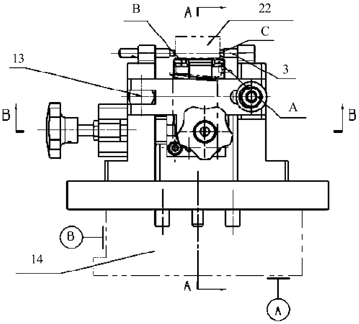
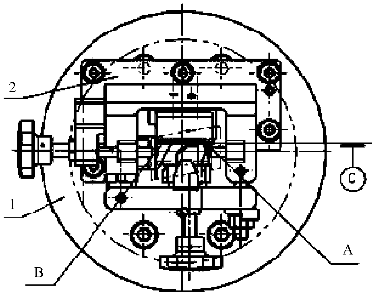
The invention discloses a positioning device and method for blade machining. The positioning device comprises an adapter plate, a supporting block, an AB point positioning block, a C point positioningpin, a D point positioning pin and an EF point positioning block. The AB point positioning block, the C point positioning pin, the D point positioning pin and the EF point positioning block are all installed on the supporting block. Moving auxiliary positioning is added, a hinge pressing mechanism is adopted, and the head and the body of the blade are pressed and operated respectively; the positioning device is novel and compact in structure, accurate in positioning, reliable in pressing, fixed in pressing position, convenient in operation, and rigid enough, the blade body is prevented from being scratched; a scheme of directly adopting a blank reference point for positioning when the turbine working blade is used for processing the tenon is realized; the machining auxiliary procedures are reduced, the cost is reduced, the machining period is shortened, the machining efficiency is improved, meanwhile, the utilization rate of the grinding wheel is increased, the design and manufacturing cost is low, the turbine working blade tenon machining requirement is completely met, and meanwhile referential experience is provided for similar problems.

Description

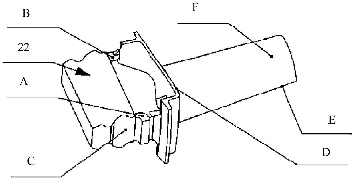
【Technical field】 [0001] The invention belongs to the technical field of manufacturing turbine working blades of aero-engines, and relates to a positioning device and method for blade processing. 【Background technique】 [0002] Turbine working blade is one of the key parts of aero-engine parts. It is composed of tenon, edge plate and airfoil. Tenon tooth processing is an important processing procedure of this part. According to the routine, low-melting point alloy is poured on the blade first, and the point positioning is transformed into After the alloy block is positioned, broaching, milling and grinding are used to process the tenon. After processing, the low-melting point alloy is melted, and pollution must be removed, resulting in high processing costs, low efficiency, and long processing cycles. Turbine working blades of a certain machine refer to figure 1 , the blade body is thicker and rigid enough. In order to reduce costs, improve efficiency, and shorten the proce...

Claims


Application Information

Patent Timeline
Patent Type & Authority Applications(China)
IPC IPC(8): B24B41/06
CPCB24B41/06
Inventor 张小莉杨琼郭相峰党玉芳李元秦瑾琦梁冬冬党小莉
Owner AECC AVIATION POWER CO LTD
Why Eureka
Try Eureka