Redundant switch control circuit and method

A technology of redundant switching and control methods, which is applied in the direction of program control, computer control, general control system, etc., can solve the problems of reduced reliability, large error switching, and trigger error switching, so as to reduce the probability of error switching and improve reliability. The effect of improving performance and reliability

Active Publication Date: 2009-08-19
ZHEJIANG SUPCON TECH
View PDF0 Cites 15 Cited by
  • Summary
  • Abstract
  • Description
  • Claims
  • Application Information

AI Technical Summary

Problems solved by technology

Due to the unfavorable factors such as complex environment, many interference sources, and high interference intensity in the industrial field, it is easy to induce interference exceeding the threshold level on the interconnection line, thereby causing the flip-flop state to flip. Due to the unique "memory" of the trigger "Effect, the error state is maintained after the interference is eliminated, so that the flip-flop is switched by mistake due to interference
[0004] It can be seen from the above that the existing redundant switching control circuit in the form of a flip-flop causes the flip-flop state to be reversed and the error state is maintained due to interference. The greater the interference, the greater the probability of mis-switching, and the lower the reliability.

Method used


Image

  • Redundant switch control circuit and method
  • Redundant switch control circuit and method

Examples


Embodiment Construction

[0035] Embodiments of the present invention provide a redundant switching control circuit and method.

[0036] In order to enable those skilled in the art to better understand the solutions of the present invention, the following will clearly and completely describe the technical solutions in the embodiments of the present invention in conjunction with the drawings in the embodiments of the present invention. Obviously, the described embodiments are only It is a part of embodiments of the present invention, but not all embodiments. Based on the embodiments of the present invention, all other embodiments obtained by persons of ordinary skill in the art without making creative efforts shall fall within the protection scope of the present invention.

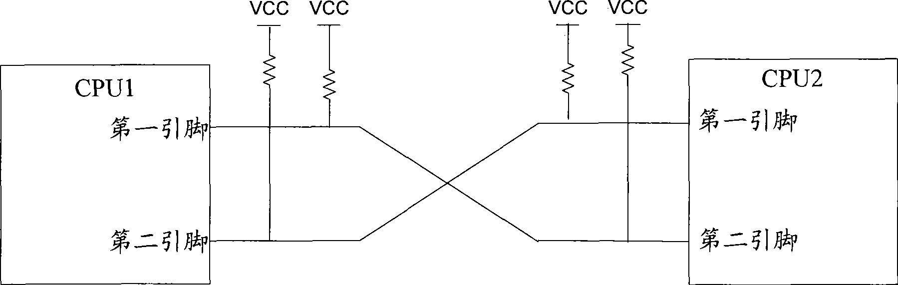
[0037] The following introduces a circuit embodiment of the redundant switching control provided by the embodiment of the present invention. The redundant switching control circuit includes two central processing units CPU1 and CPU2...


PUM


Abstract

The invention discloses a redundant switch control circuit and a method thereof. In the embodiment of the redundant switch control method, CPU1 and CPU2 adoppt a hot standby redundant configuration way; the CPU1 is in a working state; the CPU2 is in a standby state; when the CPU1 in the working state is broken down, the method comprises: the CPU1 outputs a switching request signal to the CPU2; the CPU2 receives the switching request signal; a first pin of the switching CPU2 is set to positive logic and then is detected; the state of the CPU2 is switched from the standby state to the working state; a second pin of the CPU2 is set to negative logic; a switching request signal is output to the CPU1; the CPU1 receives the switching request signal; a first pin of the CPU1 is set to negative logic and then is detected; and the state of the CPU1 is switched from the working state to the standby state. The embodiment of the invention leads the false switching rate of the redundant switch control circuit to be reduced and the reliability to be improved.

Description

technical field [0001] The invention relates to the field of automation control, in particular to a redundant switching control circuit and method. Background technique [0002] In the field of industrial automation, in order to improve the reliability of the system, some key units (or subsystems) in the system usually adopt the redundant configuration of working and standby hot backup, which is also called hot standby redundancy. configuration. In the hot standby redundant configuration, both units are set in the running state, and one of the units is set in the working state, and the other is set in the standby state. When a unit in the working state fails, the system switches between the working state and the standby state, switching the failed unit in the working state to the standby state, and switching the unit in the standby state with a lower failure level to the working state, so as to realize The switching of units with faulty working status can ensure that the u...

Claims


Application Information

Patent Timeline
Patent Type & Authority Applications(China)
IPC IPC(8): G05B19/048
Inventor 江竹轩庞欣然赖一宁
Owner ZHEJIANG SUPCON TECH
Why Eureka
Try Eureka