Fuel cell system

一种燃料电池系统、燃料电池的技术,应用在燃料电池、燃料电池助剂、电路等方向,能够解决过度放电、过度充电、二次电池老化等问题,达到不易过度放电的效果

Inactive Publication Date: 2009-09-09
TOYOTA JIDOSHA KK
View PDF1 Cites 10 Cited by
  • Summary
  • Abstract
  • Description
  • Claims
  • Application Information

AI Technical Summary

Problems solved by technology

Conversely, when overshoot occurs in the power generated by the fuel cell, overcharging that exceeds the upper limit of the charging power is likely to occur when the power generated by the supplied power is increased and the charging power of the secondary battery to be charged increases.
Therefore, when overdischarging or overcharging occurs in the secondary battery, it causes premature aging of the secondary battery
In particular, when the secondary battery is discharged close to the upper limit of the discharge power and charged close to the upper limit of the charge power, overdischarging and overcharging are likely to occur.

Method used


Image

  • Fuel cell system
  • Fuel cell system
  • Fuel cell system

Examples


no. 1 Embodiment approach

[0020] Embodiments according to the present invention will be described in detail below with reference to the drawings.

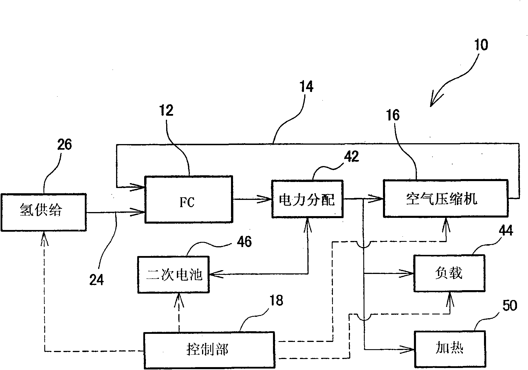
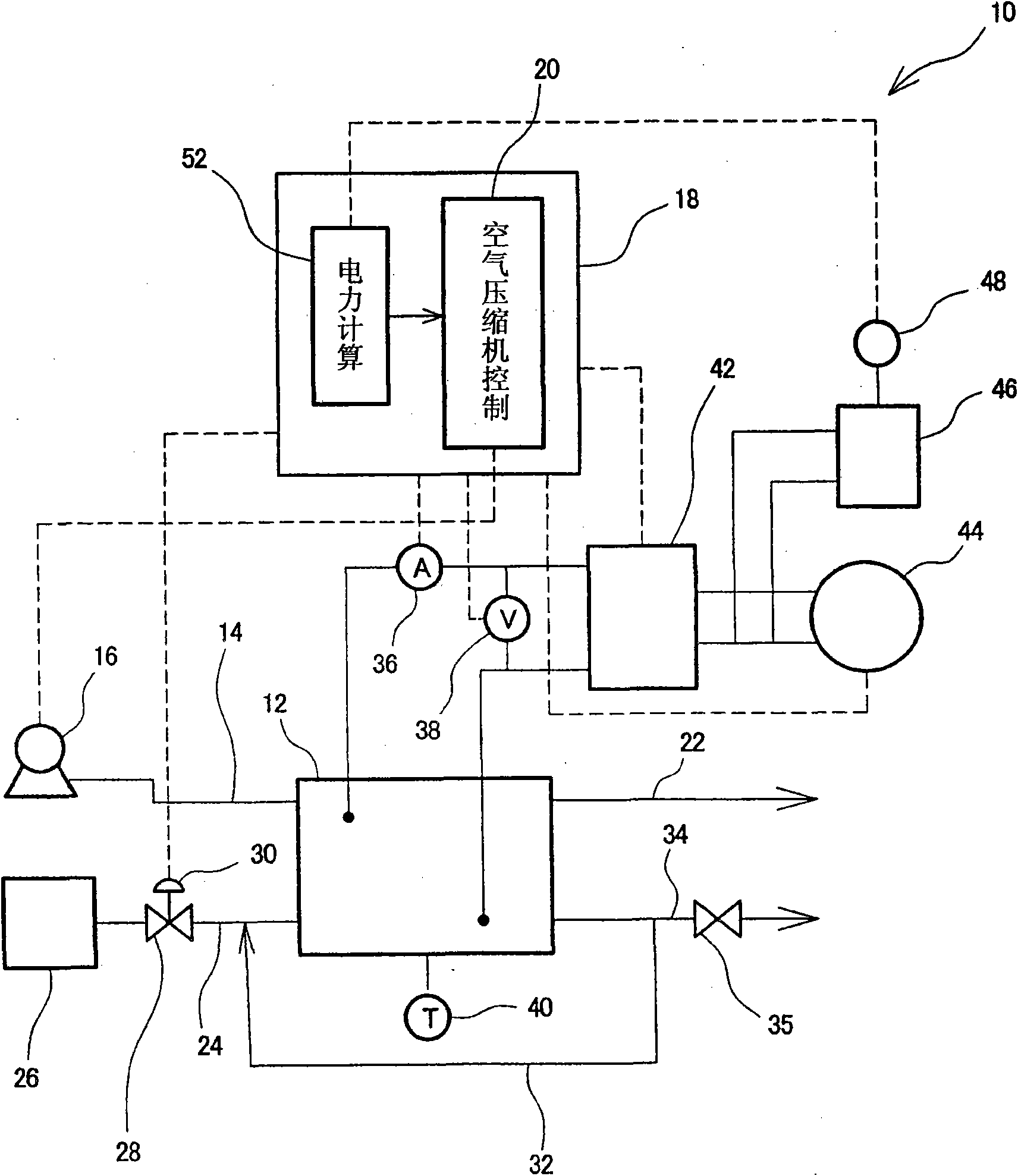
[0021] Figure 1 to Figure 4 , Figure 7 The first embodiment of the present invention is shown. figure 1 is a block diagram showing the basic configuration of the fuel cell system 10 of this embodiment, figure 2 It is also a configuration diagram showing a specific configuration.

[0022] The fuel cell system 10 of the present embodiment is used mounted on a fuel cell vehicle, and has a fuel cell stack 12 . The fuel cell stack 12 is a fuel cell stack in which a plurality of fuel cells are stacked, and collector plates and end plates are provided at both ends in the stacking direction of the fuel cell stack. Then, the fuel cell stack, current collector plates, and end plates are fastened with through bolts, nuts, and the like. In addition, an insulating plate may be provided between the collector plate and the end plate.

[0023] Detailed illustratio...

no. 2 Embodiment approach

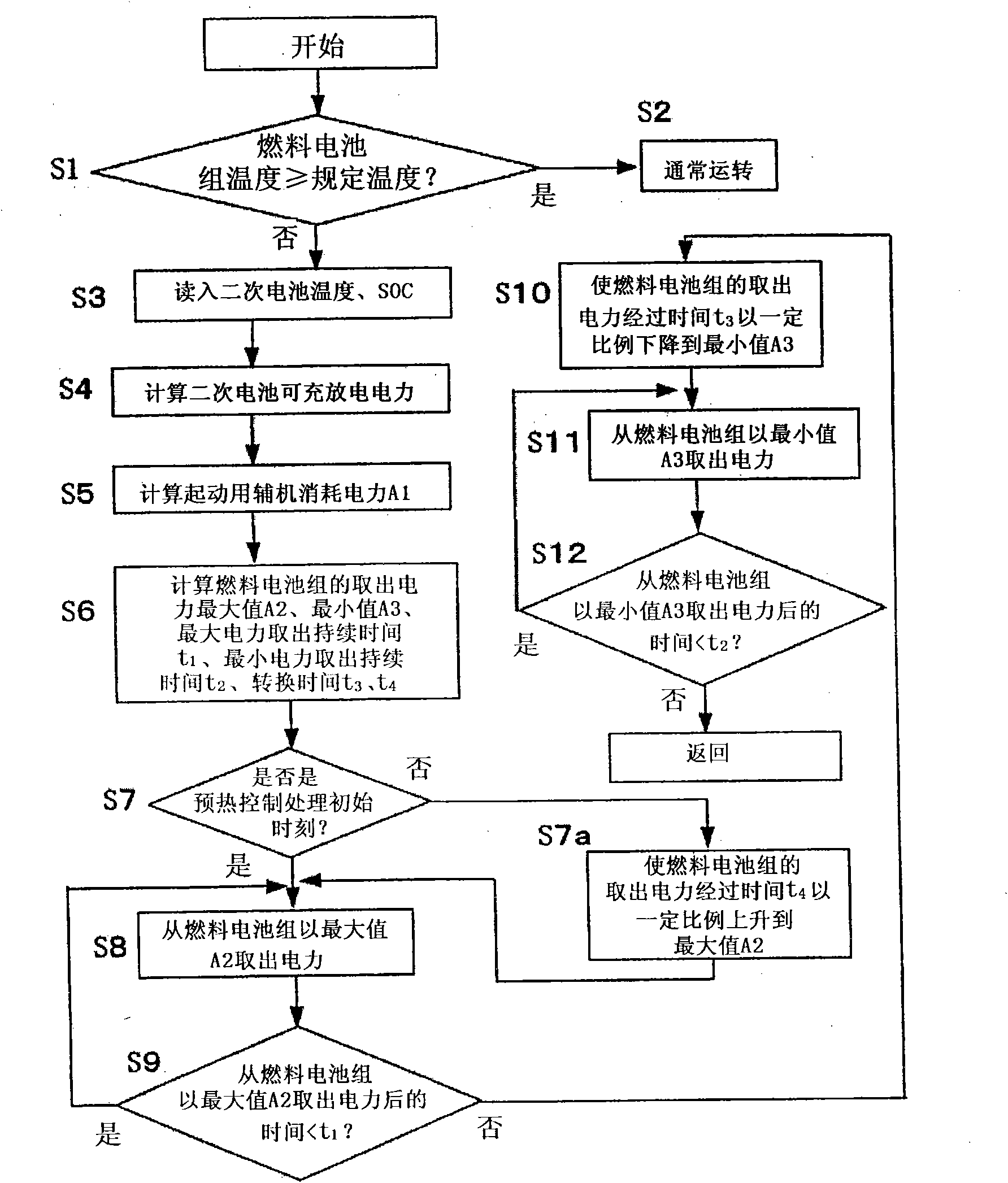
[0061] Figure 8 In the second embodiment of the present invention, the warm-up control process for warming up the secondary battery at the start of the fuel cell system is and image 3 the corresponding flowchart. In the above-mentioned first embodiment, in image 3 In step S1, the control unit 18 ( figure 1 , figure 2 ) to judge the fuel cell stack 12 ( figure 1 , figure 2 ) temperature is above the specified temperature, according to the judgment result, switch to step S2 ( image 3 ), or from step S3 ( image 3 ) transition to step S12 ( image 3 ) preheating control treatment. In contrast, in the present embodiment, whether to switch to normal operation or to warm-up control processing depends on the detected secondary battery 46 ( figure 1 , figure 2 ) is selected whether the temperature is above the specified temperature. This will be described in detail below. And, in the description below, for figure 1 , figure 2 The same reference numerals are assig...


PUM


Abstract

A fuel cell system (10) repeating first processing and second processing when the system is started. In the first processing, a control section (18) controls an electric power distribution section (42) so that electric power generated by a fuel cell stack (12) is supplied to accessories and a secondary battery (46). In the second processing, the control section (18) controls the electric power distribution section (42) so that electric power generated by the fuel cell stack (12) and electric power discharged from the secondary battery (46) are supplied to the accessories. An electric power calculation means (52) of the control section (18) calculates electric power generation by the fuel cell stack (12) and inputs an output command, representing electric power, into air compressor drive / control means (52). The electric power calculation means (52) gradually changes the magnitude of electric power generation by the fuel cell stack (12) at the time of transition between the first processing represented by the output command and the second processing.

Description

technical field [0001] The present invention relates to a fuel cell system including a fuel cell that generates electricity through an electrochemical reaction between a fuel gas and an oxidizing gas, an oxidizing gas supply unit, a secondary battery, and a power distribution unit. Background technique [0002] The fuel cell system has: a fuel gas, such as a hydrogen-containing gas; a fuel cell that generates electricity through an electrochemical reaction with an oxidizing gas, such as air; an oxidizing gas supply unit such as an air compressor that supplies the oxidizing gas to the fuel cell; rechargeable secondary battery. However, when the fuel cell system is started in a low temperature environment, the power generation performance of the fuel cell and the output characteristics of the secondary battery may decrease. [0003] In view of this situation, the fuel cell system described in Japanese Patent Application Laid-Open No. 2004-281219 includes a power distribution ...

Claims


Application Information

Patent Timeline
Patent Type & Authority Applications(China)
IPC IPC(8): H01M8/04H01M8/00
CPCH01M8/04201H01M8/04626H01M8/04768H01M8/04223Y02E60/50H01M8/04619H01M8/04947H01M8/04268H01M16/006H01M8/04225Y02E60/10
Inventor 前中健志
Owner TOYOTA JIDOSHA KK
Why Eureka
Try Eureka