Punch stripper

A technology of ejector and punch, which is applied to metal processing equipment, stripping devices, manufacturing tools, etc., and can solve the problems of large volume and difficult use of punch ejector

Inactive Publication Date: 2009-09-16
STROMSHOLMEN
View PDF10 Cites 2 Cited by
  • Summary
  • Abstract
  • Description
  • Claims
  • Application Information

AI Technical Summary

Problems solved by technology

[0022] Thus, the punch ejector shown in US 4316399 is very bulky and difficult to use in currently standardized press tools

Method used


Image

  • Punch stripper
  • Punch stripper
  • Punch stripper

Examples


Embodiment Construction

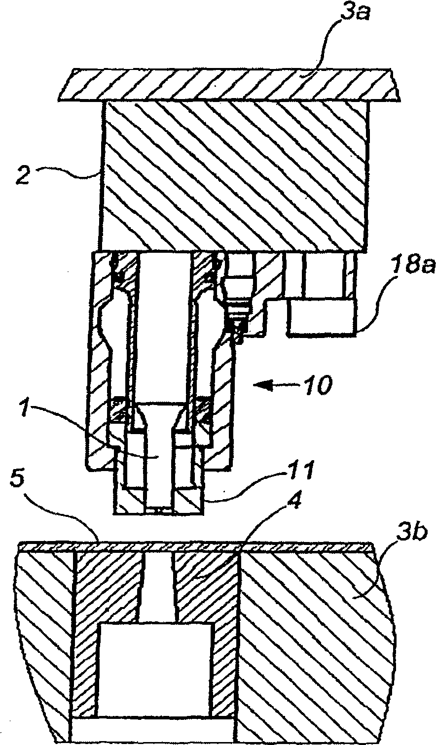
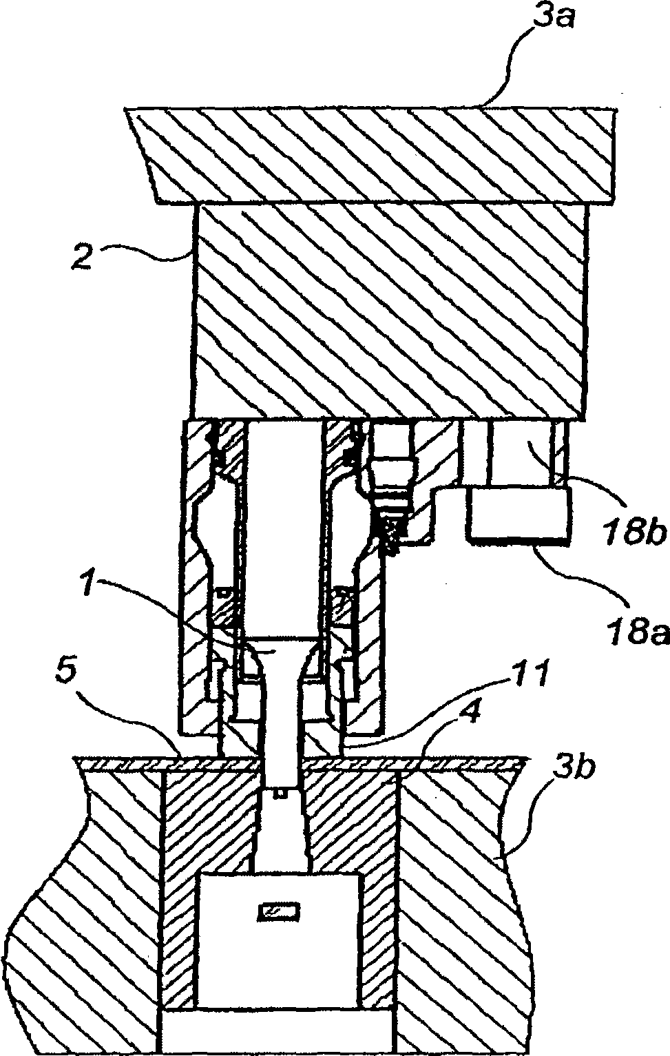
[0050] Referring now to the drawings, wherein the illustration is for the purpose of illustrating a preferred embodiment of the invention only and not for purposes of limitation, Figure 1 illustrates a press tool having an upper tool portion 3a and a lower tool portion 3b.

[0051] A punch die is provided in the lower tool part 3b. A workpiece 5, which may be a sheet metal, is arranged to be machined by the press tools 3a, 3b.

[0052] The upper tool part 3 has a punch plate 2 on which the punch 1 has a punch stripper, which is fastened by fastening means 18a, 18b (such as screws, bolts, rivets, etc.) . Such as Figure 1a , 1b As shown in and 2, the fastening means may be a mounting screw / tightening bolt 18a, the shank of which is arranged in a hole 18b in the base 14a of the punch ejector.

[0053] In a non-limiting example of the invention, the punch holder plate 2 can be designed in any of the ways disclosed in US 6182545 B1 (i.e. the punch ejector can have a locking me...


PUM


Abstract

A punch stripper is adapted to be fastened to a punch retainer of a press tool, and to retain a work piece as the piece is being machined by a punch. The punch stripper includes a punch stripper piston and a pressure chamber adapted to spring-load the punch stripper piston. The pressure chamber is at least partially defined by a gap between an inner sleeve and an outer sleeve. The punch stripper piston has a portion that is axially displaceable in the gap.

Description

[0001] Cross References to Related Applications [0002] This application claims priority to US Provisional Application Serial No. 60 / 856,837, filed November 6, 2006, which is incorporated herein by reference. This application also claims priority from Swedish Patent Application Serial No. 0602363-4 filed on November 6, 2006, which is hereby incorporated by reference. technical field [0003] The present invention relates to a punch stripper and a punching tool including the punch stripper. In particular, the invention relates to a punch ejector adapted to be fastened to a punch retainer mountable to a movable upper tool part of a press. Background technique [0004] In the sheet metal forming industry, punching tools are used to punch holes in sheet metal. The punching tool mainly includes a fixing plate, a punching machine and a stripper. The punching tool operates as a closed unit and is usually mounted directly into the press tool where the sheet metal is formed, but ...

Claims


Application Information

Patent Timeline
IPC IPC(8): B21D45/00
CPCB21D45/006B21D45/08
Inventor 弗雷德里克·埃克曼帕特里克·施托尔茨
Owner STROMSHOLMEN
Why Eureka
Try Eureka