Differential pressure type flow sensor capable of realizing direct pressure tapping and two-way measurement

A flow sensor and two-way measurement technology, which is applied in the direction of detecting fluid flow by measuring pressure difference, volume/mass flow generated by mechanical effects, etc., can solve the problems of high installation requirements, low measurement accuracy, and large floor space. Achieve good long-term stability, high measurement accuracy, and reduce floor space

Inactive Publication Date: 2009-09-23
JINZHOU NORTH NAUTICAL INSTR
View PDF0 Cites 9 Cited by
  • Summary
  • Abstract
  • Description
  • Claims
  • Application Information

AI Technical Summary

Problems solved by technology

[0003] (1) The measurement accuracy is generally low;
[0004] (2) The range is relatively narrow, generally only 3:1 to 4:1;
[0005] (3) High requirements for on-site installation conditions;
[0006] (4) Large pressure loss (such as orifice plate, nozzle, etc.)
[0007] In addition, the differential pressure flowmeter in the prior art can only measure the flow in one direction. In order to realize the two-way measurement, two differential pressure transmitters and two sets of pressure guide conduit systems need to be installed, which takes up more space and makes the installation more complicated.

Method used


Image

  • Differential pressure type flow sensor capable of realizing direct pressure tapping and two-way measurement
  • Differential pressure type flow sensor capable of realizing direct pressure tapping and two-way measurement
  • Differential pressure type flow sensor capable of realizing direct pressure tapping and two-way measurement

Examples


Embodiment Construction

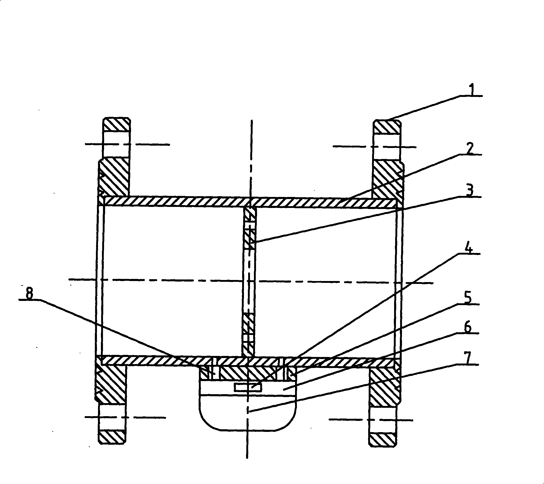
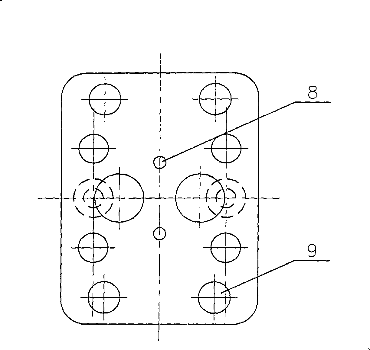
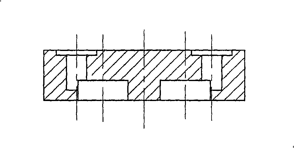
[0024] like figure 1 As shown, the present invention has a tubular housing 2, flanges 1 for connecting with the measured pipeline are welded at both ends of the housing 2, and double-sided symmetrical throttle plates 3 are welded in the housing 2; as figure 1 , figure 2 and image 3 As shown, two pressure introduction holes 8 are processed on the pipe wall of the shell 2, and the said pressure introduction holes 8 are located on the front and rear sides of the double-sided symmetrical throttle plate 3, and on the shell 2 corresponding to the pressure introduction holes 8 A pressure-taking membrane box 6 is installed through a connecting plate 5, and pressure introduction holes are processed on the connecting plate 5 and the pressure-taking membrane box 6; Surface pressure-taking type differential pressure transmitter 4 (3051), outside the pressure-taking membrane box 6 is also connected with a differential pressure flow converter 7 with a flow output of 4-20mA and a zero po...


PUM


Abstract

The invention relates to a differential pressure type flow sensor capable of realizing direct pressure tapping and two-way measurement, which solves the problems that a differential pressure type flowmeter must be provided with a pressure guiding pipe, has large occupation space, lower measuring precision and narrower range and can only measure flow along one direction in prior art. The differential pressure type flow sensor is characterized in that a shell is internally welded with a throttle disc with symmetrical double surfaces, a pipe wall of the shell is provided with pressure guiding hole, the shell is provided with a pressure tapping sylphon corresponding to the pressure guiding hole, the pressure tapping sylphon is internally provided with a coplanar pressure tapping type differential pressure transmitter with the precision of 0.04 percent, and the pressure tapping sylphon is also externally connected with a differential pressure flow converter which can realize the two-direction measurement of flow, has flow output ranged from 4 to 20 mA and a zero point of 12 mA. The invention has the advantage that the pressure tapping sylphon is attached to the wall of the shell so as to omit the traditional pressure guiding pipe, thereby having compact structure, eliminating the standstill space of bubbles on mechanism and overcoming the flow measurement fluctuation caused in such a way that the bubbles stop in the pressure guiding pipe, and the differential pressure transmitter can realize positive and negative two-direction flow measurement.

Description

technical field [0001] The invention belongs to a differential pressure flow sensor, in particular to a differential pressure flow sensor which is suitable for measuring the flow of liquid, gas and vapor and can realize direct pressure acquisition and bidirectional measurement. technical background [0002] Differential pressure flowmeter is the most typical and most widely used flow sensor for flow detection at home and abroad. The differential pressure flowmeter in the prior art must be equipped with a pressure guide conduit, which is connected to the differential pressure transmitter through the pressure guide conduit. When the instrument is put into operation for the first time, bubbles will be trapped in the pressure guide conduit, causing measurement errors; and the pressure guide conduit The installation of the vertical or horizontal planes should be kept at an inclination of not less than 1:10, and gas, condensate, particle collectors and settlers need to be installe...

Claims


Application Information

Patent Timeline
Patent Type & Authority Applications(China)
IPC IPC(8): G01F1/36
Inventor 徐超鲍海阁庄廷敏王建辉刘义
Owner JINZHOU NORTH NAUTICAL INSTR
Why Eureka
Try Eureka