Supercharge Your Innovation With Domain-Expert AI Agents!

Zoom lens system, optical equipment and method for manufacturing zoom lens system

A technology of variable magnification lens and manufacturing method, applied in optics, optical components, instruments, etc., can solve problems such as inability to achieve optical performance

Inactive Publication Date: 2009-10-07
NIKON CORP
View PDF1 Cites 4 Cited by
  • Summary
  • Abstract
  • Description
  • Claims
  • Application Information

AI Technical Summary

Problems solved by technology

[0003] However, there is a problem that the existing variable power lens system cannot achieve good optical performance

Method used


Image

  • Zoom lens system, optical equipment and method for manufacturing zoom lens system
  • Zoom lens system, optical equipment and method for manufacturing zoom lens system
  • Zoom lens system, optical equipment and method for manufacturing zoom lens system

Examples


no. 2 approach

[0220] A preferred second embodiment of the present invention will be described below with reference to the drawings. In this specification, unless otherwise specified, the wide-angle end state and the telephoto end state refer to the state in the infinity focus state. Such as Figure 23 As shown, the variable power lens system ZL includes in order from the object side along the optical axis: the first lens group G1 with positive refractive power, the second lens group G2 with negative refractive power, the third lens group G3 with positive refractive power, and the third lens group G3 with positive refractive power. The fourth lens group G4 with negative refractive power, and the fifth lens group G5 with positive refractive power. When changing the magnification from the wide-angle end state to the telephoto end state, the distance between the first lens group G1 and the second lens group G2 changes, the distance between the second lens group G2 and the third lens group G3 c...

no. 1 example

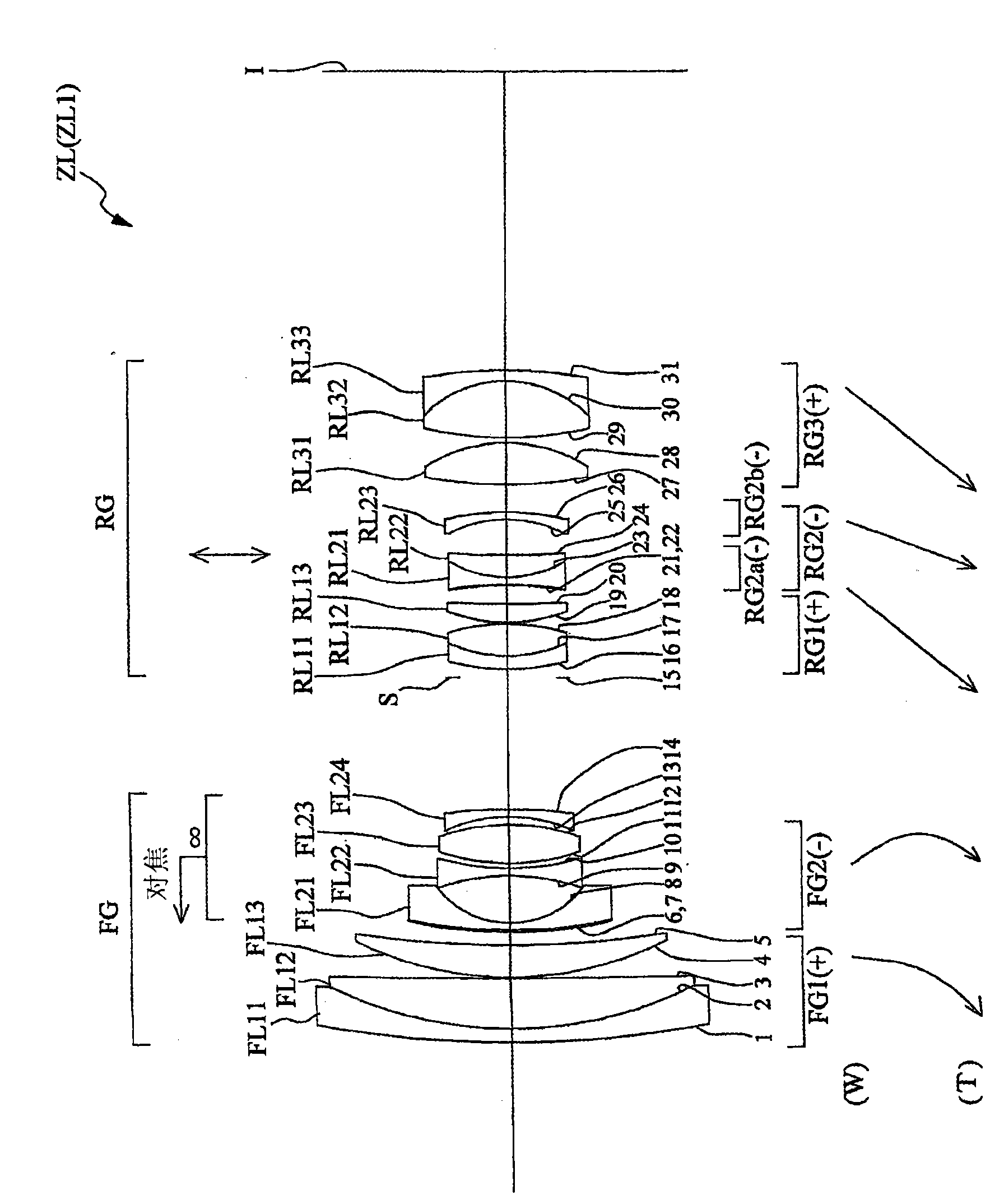
[0275] figure 1 It is a diagram showing the configuration of the variable power lens system ZL1 of the first embodiment. Should figure 1 The variable magnification lens system ZL1 includes in order from the object side: the front part lens group FG1 with positive refractive power; the rear part lens group FG2 with negative refractive power; the first lens group RG1 with positive refractive power; the part 2a with negative refractive power The lens group RG2a; the 2b portion lens group RG2b having a negative refractive power; and the third lens group RG3 having a positive refractive power. In the variable power lens system ZL1, when the lens position changes from the wide-angle end state to the telephoto end state, the air gap between the front part lens group FG1 and the rear part lens group FG2 changes, and the rear part lens group FG2 and the first lens group RG1 The air interval of the first lens group RG1 and the second part lens group RG2a is changed (increased) from d1...

no. 2 example

[0372] Figure 5 It is a figure which shows the structure of the variable power lens system ZL2 of 2nd Example. Should Figure 5 The variable magnification lens system ZL2 includes, in order from the object side: the front part lens group FG1 with positive refractive power; the rear part lens group FG2 with negative refractive power; the first lens group RG1 with positive refractive power; the part 2a with negative refractive power The lens group RG2a; the 2b portion lens group RG2b having a negative refractive power; and the third lens group RG3 having a positive refractive power. In this variable power lens system ZL2, when the lens position state changes from the wide-angle end state to the telephoto end state, the air gap between the front part lens group FG1 and the rear part lens group FG2 changes, and the rear part lens group FG2 and the first lens group RG1 The air interval of the first lens group RG1 and the second part lens group RG2a is increased from d12w to d12t...


PUM


Abstract

The present invention provides a zoom lens system, optical equipment having the zoom lens system and a method for manufacturing the zoom lens system. The zoom lens system of the invention is composed of a front lens set and a rear lens set in sequence from an object side, wherein the rear lens set includes a first lens assembly having a positive refractive power, a second lens assembly having a negative refractive power and a third lens assembly having a positive refractive power, when the lens position state changes from a pantoscopic end status to a farend status, the interval of the front lens set and the first lens assembly is altered, the interval of the first lens assembly and the second lens assembly is increased, the interval of the second lens assembly and the third lens assemblyis decreased, the second lens assembly is configured that at least part of the second lens assembly may move, such that the second lens assembly has a component in a direction vertical to the opticalaxis.

Description

technical field [0001] The invention relates to a variable power lens system, an optical device with the variable power lens system and a manufacturing method of the variable power lens system. Background technique [0002] Conventionally, variable magnification lens systems suitable for photographic cameras, electronic still cameras, video cameras, etc. have been proposed (for example, refer to JP-A-2006-85155). With reference to JP Unexamined Publication No. 2006-85155, in particular, a variable magnification lens system suitable for photographic cameras, electronic still cameras, video cameras, etc. has been proposed: by moving a part of the lens, there is a component in a direction perpendicular to the optical axis, The position of the image can be changed. [0003] However, the existing variable power lens system has the problem that good optical performance cannot be achieved. Contents of the invention [0004] In view of such a problem, the present invention aims ...

Claims


Application Information

Patent Timeline
IPC IPC(8): G02B15/16
Inventor 山口悟史
Owner NIKON CORP
Features
  • R&D
  • Intellectual Property
  • Life Sciences
  • Materials
  • Tech Scout
  • Unparalleled Data Quality
  • Higher Quality Content
  • 60% Fewer Hallucinations
Learn More