Particle or aerosol gathering unit of office machine

A technology for collecting devices and particles, used in printing devices, instruments, electrographics, etc., to solve the problems of inability to collect or remove inkjet aerosols or particles, and inability to absorb paper dust.

Inactive Publication Date: 2009-10-21
KINPO ELECTRONICS
View PDF6 Cites 8 Cited by
  • Summary
  • Abstract
  • Description
  • Claims
  • Application Information

AI Technical Summary

Problems solved by technology

However, as those who are familiar with this technology know, there are still some problems in the application of this dust collection device that need to be improved; for example, it can only absorb the dust on one side of the paper, but cannot

Method used


Image

  • Particle or aerosol gathering unit of office machine
  • Particle or aerosol gathering unit of office machine
  • Particle or aerosol gathering unit of office machine

Examples


Embodiment Construction

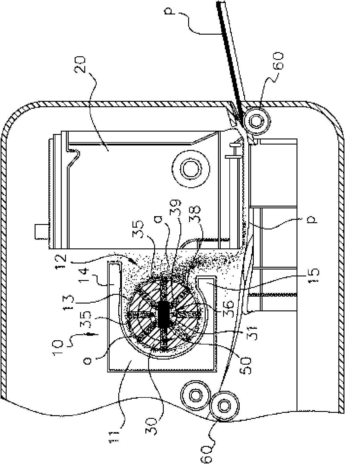
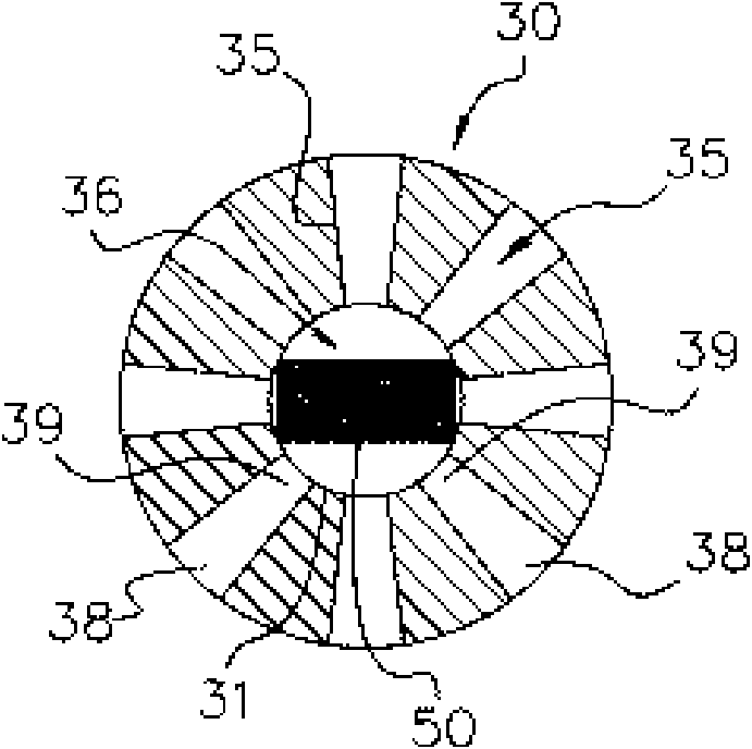
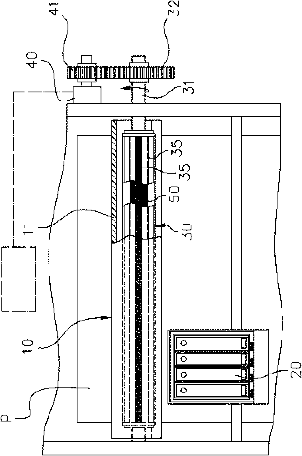
[0032] see figure 1 , figure 2 and image 3 , the present invention is a particle or aerosol collection device for an office machine, including a collection device, generally represented by reference number 10 . Said collecting device 10 is arranged on the position close to a printing part or printing head 20, comprises a housing 11 with opening 12; Housing 11 has an upper part 14 and lower part 15, and defines a space 13, configures an absorbing Part 30 is used to attract or collect particles or ink aerosols a that are scattered in the air.

[0033] Please refer to image 3 , the absorption part 30 is driven by a motor 40 and can rotate freely; and with the rotation of the absorption part 30, the air is brought into the absorption part 30, and a negative pressure effect is established in the vicinity of the absorption part 30 to guide or collect volatile Particles or ink aerosol a scattered in the air inside the business machine move to the absorbing portion 30 . In the...


PUM


Abstract

The invention relates to a particle or aerosol gathering unit of an office machine which is arranged on a position close to a printing department or a printing head, comprises a shell with an opening and a cleaning unit deployed in an absorption part; the shell has a space so as to be deployed with an absorption part provided with a plurality of passages; the absorption part is driven by a motor to freely rotate and oppositely generates the negative pressure effect to lead or collect particles or printing ink aerosol volatile in air to enter into the absorption part along the passages; in the course of the rotation of the absorption part, the cleaning unit collects or clears the particles or the printing ink aerosol so as to prevent the particles or the printing ink aerosol from effecting the printing quality.

Description

Technical field: [0001] The present invention relates to a particle or aerosol collecting device; in particular, it refers to a means for collecting volatilized ink aerosol with a rotatable device installed in a business machine. Background technique: [0002] A business machine for making paper documents available for printing or printing is known; for example, a printing press or printer. Basically, they provide a printhead, which is positioned at a set height above the surface of the paper passing through it; and which reciprocates in a direction perpendicular to the paper feed, causing the printhead to eject ink droplets to form an image on the paper. [0003] Typically, a printhead system has a number of nozzles for ejecting ink; as those skilled in the art know, as the nozzles repeatedly eject ink onto the paper, some ink droplets will remain and collect around the nozzles, eventually forming Solid deposits block part of the nozzle, thereby changing the direction of i...

Claims


Application Information

Patent Timeline
IPC IPC(8): B41J29/17B41J2/165G03G21/00
Inventor 赖逸林潘天佑陈铎壬
Owner KINPO ELECTRONICS
Why Eureka
Try Eureka