Unlock instant, AI-driven research and patent intelligence for your innovation.

Bicycle with clutch transmission function system

A clutch transmission, bicycle technology, applied in clutches, mechanically driven clutches, clutches that mesh with each other, etc., can solve problems such as inconvenient use, and achieve the effect of reversing

Inactive Publication Date: 2009-10-21
JINN JINN IND
View PDF1 Cites 2 Cited by
  • Summary
  • Abstract
  • Description
  • Claims
  • Application Information

AI Technical Summary

Problems solved by technology

[0005] However, there are still problems with this structure. Because the socket wrench is driven by the circular motion of the pedal, no matter whether the pedal is rotating forward or reverse, the socket wrench will swing up and down in the same way, driving the rear wheel forward, so the rear wheel It cannot go backwards, but can only move forward in one direction. Therefore, the above-mentioned bicycle can only go forward and cannot go backward. This kind of bicycle is extremely inconvenient for users to use.

Method used


Image

  • Bicycle with clutch transmission function system
  • Bicycle with clutch transmission function system
  • Bicycle with clutch transmission function system

Examples


Embodiment Construction

[0029] Below with regard to the structural composition and the effect that can produce of the bicycle of tool clutch transmission action system of the present invention, cooperate accompanying drawing to describe in detail as follows with preferred embodiment:

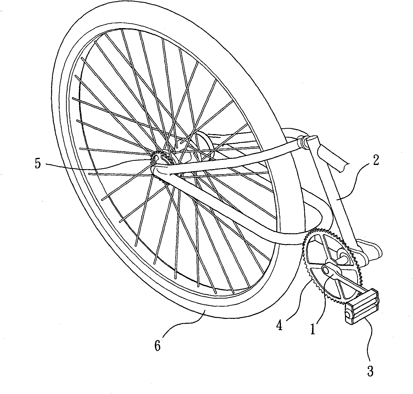
[0030] see Figure 2-5 Shown is a preferred embodiment of the present invention, a bicycle 100 with a clutch transmission system, which includes a vehicle frame 10, a front wheel 20, a rear wheel 30 and a clutch transmission system 40;

[0031] Wherein vehicle frame 10 is identical with the vehicle frame structure of existing bicycle;

[0032] Wherein the front wheel 20 is pivotally arranged below the front end of the vehicle frame 10, and the front wheel 20 rotates with the pivot point as the axis;

[0033] Wherein the rear wheel 30 is pivotally arranged below the rear end of the vehicle frame 10, and the rear wheel 30 rotates with the pivot point as the axis;

[0034] Wherein the clutch transmission action system 4...


PUM


Abstract

The invention discloses a bicycle with a clutch transmission function system which comprises a frame and the clutch transmission function system. The clutch transmission function system comprises a treading device, a fluted disc device, a swinging linkage device and a clutch device. The treading device arranged on the frame is used for treading for users to perform circular motion. The fluted disc device is provided with a transmission shaft and a fluted disc, the transmission shaft is pivoted on the frame, and the fluted disc is sleeved on the transmission shaft and can rotate relative to the transmission shaft. The swinging linkage device connecting the treading device and the fluted disc device is used for increasing the torque of the rotary power of the treading device through swinging and transmitting the rotary power to the transmission shaft of the fluted disc device. The clutch device arranged on the frame can be controlled to combine the fluted disc with the transmission shaft or separate the fluted disc from the transmission shaft to satisfy the use requirement of different states for users and can move (such as the states of back-off and pulling) the bicycle so as to solve the inconvenience problem in use.

Description

technical field [0001] The invention relates to a bicycle, in particular to a bicycle with a clutch transmission system. Background technique [0002] General existing bicycle transmission mode mainly is to utilize the circular type pedaling mode to drive the rear wheel to rotate. Such as figure 1 As shown, one end of the crank 1 is connected to the frame 2, and the other end is sleeved with a pedal 3. When the user depresses the pedal 3 to perform circular rotation, the crank 1 drives the toothed plate 4 to rotate, and is engaged with the The chain (not shown) on the chainring 4 synchronously drives the flywheel 5 that is located at the rear position of the vehicle frame 2 to rotate, and the flywheel 5 drives the rear wheel 6 to rotate, thereby making the bicycle move. However, since the torque of this transmission mode mainly comes from the force applied by the user stepping on the pedal, and then converted by the moment arm of the crank, and the length of the crank is l...

Claims


Application Information

Patent Timeline
Patent Type & Authority Applications(China)
IPC IPC(8): B62M1/04B62M1/02B62M1/24B62M1/36
CPCF16D11/10B62M1/26
Inventor 林进锦
Owner JINN JINN IND
Features
  • R&D
  • Intellectual Property
  • Life Sciences
  • Materials
  • Tech Scout
  • Unparalleled Data Quality
  • Higher Quality Content
  • 60% Fewer Hallucinations
Learn More