Projection zoom lens and projection type display apparatus

一种变焦透镜、透镜的技术,应用在光学元件、光学、仪器等方向,能够解决广角端狭窄、难以谋求透镜系统小型化、轻量化等问题,达到像差良好的效果

Inactive Publication Date: 2009-10-21
FUJI PHOTO OPTICAL CO LTD
View PDF3 Cites 5 Cited by
  • Summary
  • Abstract
  • Description
  • Claims
  • Application Information

AI Technical Summary

Problems solved by technology

[0009] However, although the projection zoom lenses described in the above-mentioned Patent Document 1 and the above-mentioned Patent Document 2 are relatively small, they have a dark F value of 2.0 or more at the wide-angle end, and a narrow field of view at the wide-angle end of 50° or less.
[0010] Furthermore, the projection zoom lens described in Patent Document 3 is bright with an F value of 1.6 at the wide-angle end and wide-angled at a field angle of 55° at the wide-angle end, but the first lens group with the largest lens outer diameter Using three lenses makes it difficult to reduce the size and weight of the entire lens system

Method used


Image

  • Projection zoom lens and projection type display apparatus
  • Projection zoom lens and projection type display apparatus
  • Projection zoom lens and projection type display apparatus

Examples


Embodiment 1

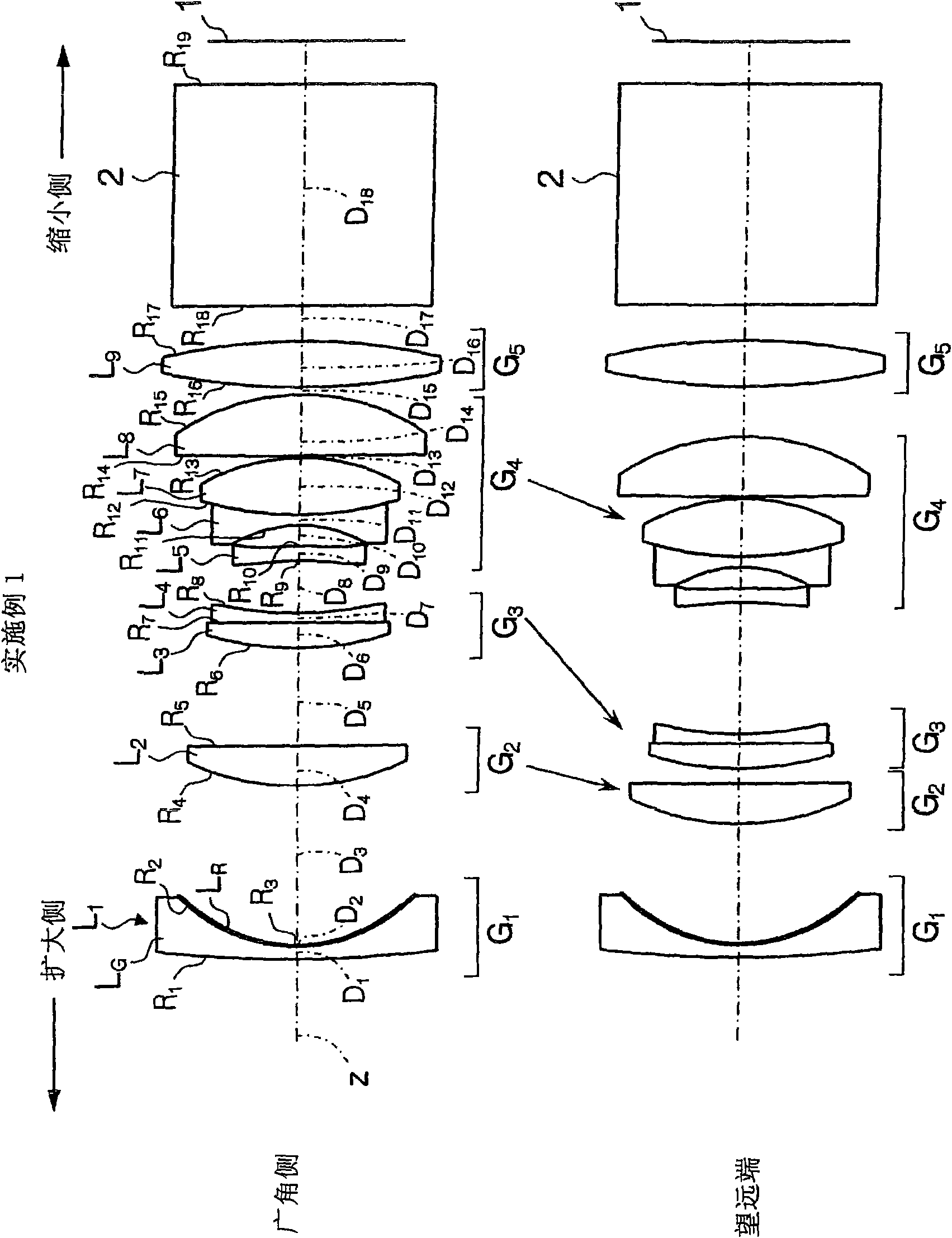
[0109] The projection zoom lens related to this Embodiment 1 is set as described above figure 1 structure shown. That is, in the zoom lens for projection, the first lens group G 1 only by passing through the glass lens L G The surface of the resin layer L is closely bonded to form R And the resin layer L R The first lens L composed of a composite aspheric lens formed with an aspheric surface at the interface with air 1 Composition, second lens group G 2 Second lens L consisting only of a positive meniscus lens with a convex surface facing the magnification side 2 Composition, third lens group G 3 Contains third lens L consisting of a positive meniscus lens with a convex surface facing the magnification side 3 And the fourth lens L consisting of a negative meniscus lens whose concave surface faces the reduction side 4 . Furthermore, the fourth lens group G 4 Contains 5th lens L with aspheric surfaces on both sides of the concave surface facing the magnification side ...

Embodiment 2

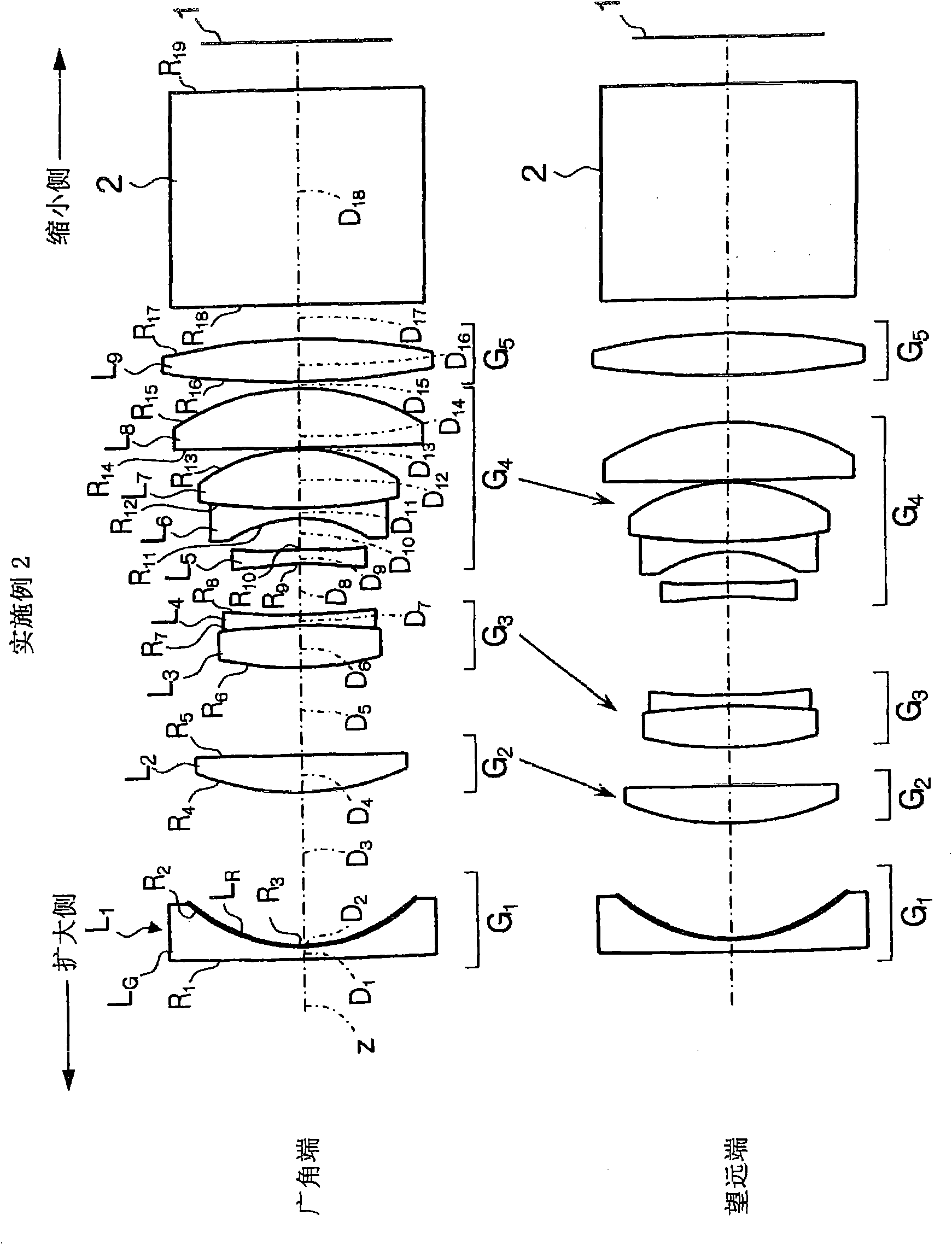
[0127] exist figure 2 The schematic configuration of the projection zoom lens according to the second embodiment is shown. The projection zoom lens related to this second embodiment has substantially the same structure as that of the first embodiment, and the main difference is that the second lens L 2 Consists of biconvex lens, third lens L 3 I consist of a biconvex lens, and the fourth lens L 4 Consists of biconcave lenses.

[0128] Table 2 shows the radius of curvature R of each lens surface, the center thickness of each lens, the air space D between each lens, the refractive index Nd of the d-line of each lens, and the Abbe number vd of each lens in Example 2.

[0129] [Table 2]

[0130] face number

R

D

N d

v d

1

25.778

0.072

1.58913

61.1

2

0.952

0.008

1.52771

41.8

3*

0.829

(variable 1)

4

1.520

0.216

1.83400

37.2 ...

Embodiment 3

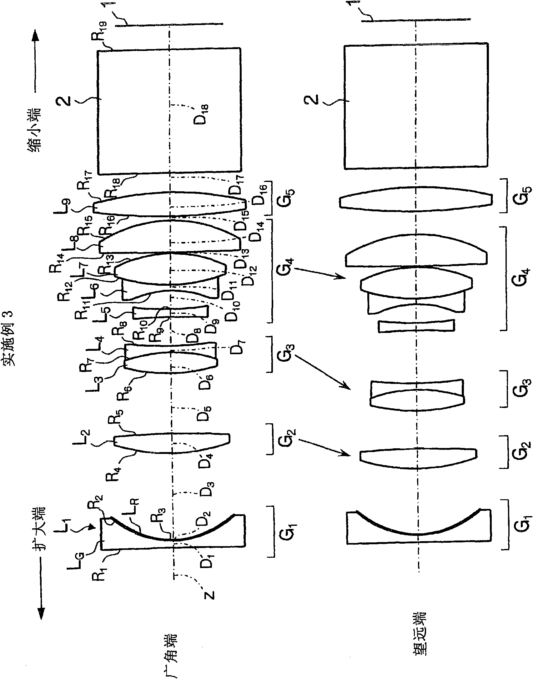
[0141] exist image 3 The schematic configuration of the projection zoom lens according to the third embodiment is shown. The projection zoom lens according to the third embodiment has substantially the same configuration as that of the second embodiment, but the main difference from the second embodiment is that the first lens L 1 Consists of biconcave lenses.

[0142] Table 3 shows the radius of curvature R of each lens surface, the center thickness of each lens, the air space D between each lens, the refractive index Nd of the d-line of each lens, and the Abbe number vd of each lens in Example 3.

[0143] [table 3]

[0144] face number

R

D

N d

v d

1

-62.674

0.072

1.58913

61.1

2

0.924

0.008

1.52771

41.8

3*

0.804

(variable 1)

4

1.817

0.200

1.83400

37.2

5

-8.443

(variable 2)

6

1.769 ...


PUM


Abstract

The invention provides a projection zoom lens, which has nine lenses in five groups. The first group is set as simple structure with the F value of wide-angle end lower than 1.7 and field angle more than 55 degree, which can well modifies various aberration and is cheap and smart. The projection zoom lens includes a first lens group (G) having a negative reflecting power and a second to fifth lens groups (G-G) each having a positive reflecting power are provided in the order from the reduction side. Nine lenses are distributed in a manner that the first lens group (G) has one lens, the second lens group (G) has one lens, the third lens group (G) has two lenses, the fourth lens group (G) has four lenses and the fifth lens group (G) has one lens. Since the second lens group (G), the third lens group (G) and the fourth lens group (G) are moved at the time of the power-varying operation, various kinds of aberrations may be made despite of simple configuration. Furthermore, the first lens group (G) is an aspherical lens which concave surface is directed to the reduction side.

Description

technical field [0001] The present invention relates to a compact projection zoom lens with a structure of 5 groups and 9 elements loaded in a projection display device and the projection display device loaded with the projection zoom lens. A zoom lens for projection and a projection display device that are used especially when light beams of image information from a light valve such as a transmissive or reflective liquid crystal display device or a DMD (Digital Micromirror Device) display device are enlarged and projected onto a screen from the front side. Background technique [0002] In recent years, projection display devices using light valves, such as liquid crystal display devices and DMD display devices, have been widely used. In particular, a structure in which each illumination light is modulated by using three light valves and corresponding to the illumination lights of RGB3 primary colors is widely used. , Combining the light modulated by each light valve with a ...

Claims


Application Information

Patent Timeline
Patent Type & Authority Applications(China)
IPC IPC(8): G02B15/177G02B13/22G02B13/18G02B27/18
CPCG02B15/177G02B13/16G02B15/145531
Inventor 永利由纪子
Owner FUJI PHOTO OPTICAL CO LTD
Why Eureka
Try Eureka