

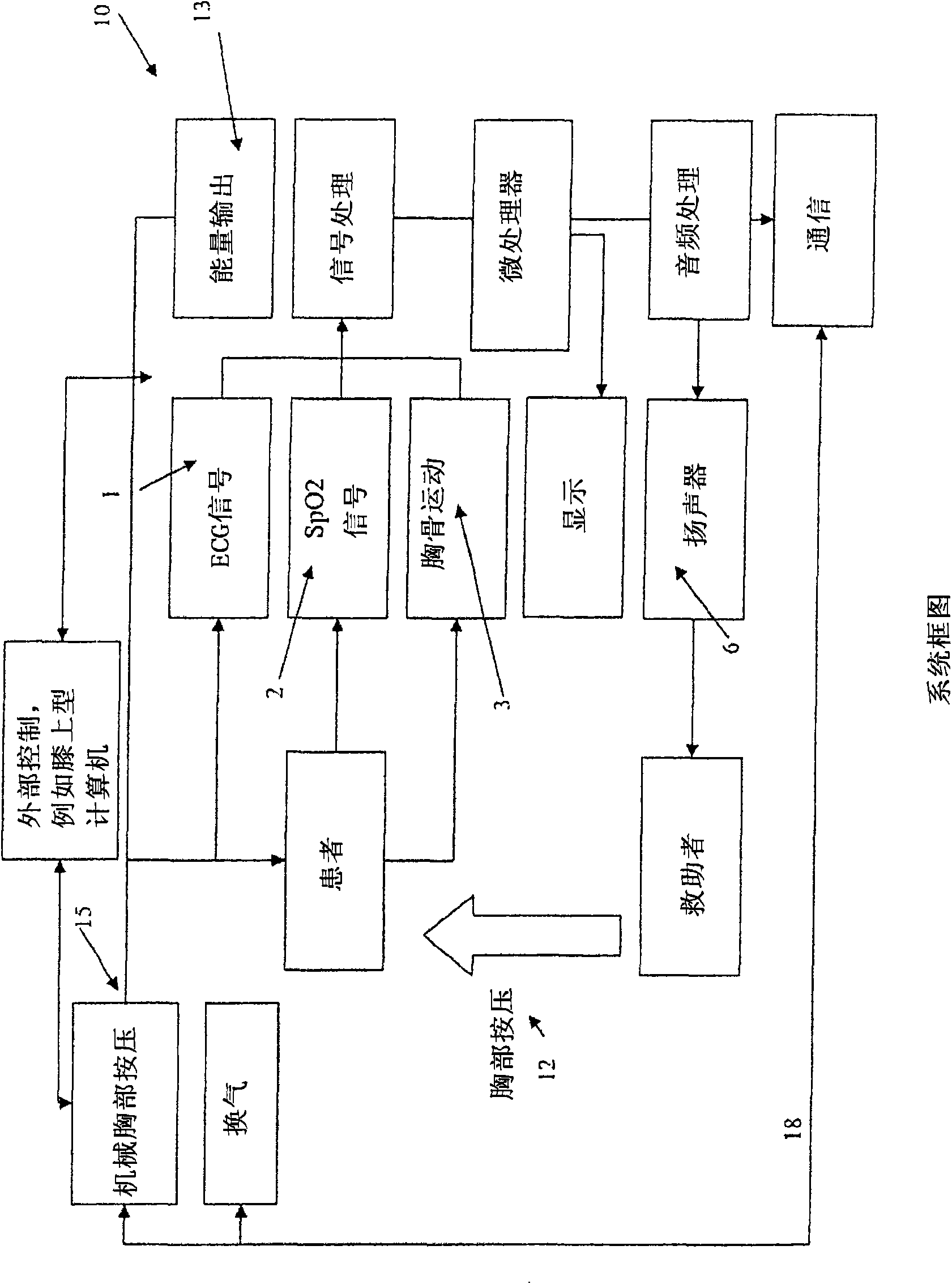
Synchronization of defibrillation and chest compressions
A technology of defibrillation and defibrillator, which is applied in the field of medical devices and can solve problems such as beneficial effect assumptions
- Summary
- Abstract
- Description
- Claims
- Application Information
AI Technical Summary
Problems solved by technology
Method used
Image

Examples
Embodiment Construction
[0015] The invention has many different embodiments, too many to be described here. Some possible embodiments that are presently preferred are described below. Although it cannot be overemphasized, these are exemplary descriptions of embodiments of the invention, not a description of the invention, and the invention is not limited to the detailed embodiments described in this section, but rather in broader terms in the claims to describe.
[0016] The discovery that a defibrillation shock should be synchronized with the early part of the decompression (diastolic) phase of chest compressions was partly a result of a new method developed by the inventors for testing the defibrillation threshold (DFT). When comparing the efficacy of a therapeutic intervention to an experimental control in an animal model, the DFT is measured separately for the treatment and control, and then the DFT levels are compared. The so-called DFT50 is the defibrillation energy for a specific therapy at ...
PUM
 Abstract
Description
Claims
Application Information