Supercharge Your Innovation With Domain-Expert AI Agents!

A flexible lamp

A light tube and flexible technology, applied in the field of lighting devices, can solve the problems of relatively large PCB board limitation, signal attenuation, complicated wiring, etc., and achieve the effect of small and thin overall structure of the light tube, eliminating accumulated signal deviation and stable transmission signal.

Inactive Publication Date: 2012-02-08
范红霞
View PDF3 Cites 0 Cited by
  • Summary
  • Abstract
  • Description
  • Claims
  • Application Information

AI Technical Summary

Problems solved by technology

[0003] In the prior art, the lamp tubes are connected in series from end to end, and the lamp tubes are usually cascaded in series through four signal lines. This connection method greatly limits the application of the lamp tube as a display surface ;The lamp tubes are cascaded through four signal wires, and the power and ground wires need to be cascaded with six wires. Because there are too many connectors in the line, the reliability is not high, and the restrictions on the PCB board are relatively large. The wires from the ends of the tubes are pulled to the front so that they can be connected to each other at one end, which will make the wiring very complicated and difficult to route; When there is an error in the driver chip in the first lamp tube, it will cause the lamp tubes connected behind to fail to work normally.
[0004] The Chinese patent "Flexible Light Strip Embedded with Serial Drive Control Chip" (Chinese Patent Application No.: 200410070987.0) discloses a flexible light strip with embedded serial drive control chip, which independently controls the LED lights through the serial drive control chip. The brightness adjustment of a single lamp solves the common problems of the above-mentioned LED flexible decorative lamps. However, since the serial drive control chip of the invention uses four traditional control signal lines for transmission, it is easy to cause problems between lines during transmission. Signal interference, and there will be signal attenuation during signal transmission

Method used


Image

  • A flexible lamp
  • A flexible lamp
  • A flexible lamp

Examples


Embodiment Construction

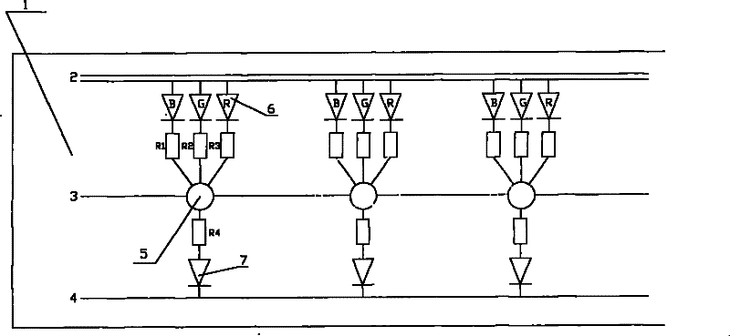
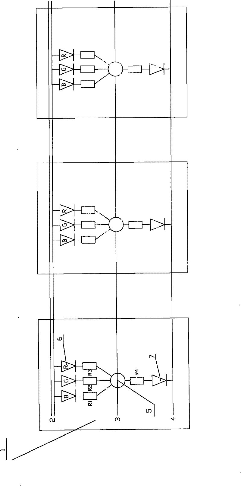
[0028] figure 1 Shows the first embodiment of the present invention, on the flexible PCB board 1 is provided with: LED light emitting unit 6, the light emitting unit 6 is composed of red light emitting diode, green light emitting diode, blue light emitting diode, respectively connected with resistors R1, R2, R3 is connected in series; the single-line transmission drive control chip 5 inputs a control signal through a signal control line 3 to directly drive and control the LED light-emitting unit 6 on the flexible PCB 1 to emit light. An LED error indicator 7 is also arranged on the flexible PCB 1, which is connected in series with the resistor R4. The LED error indicator 7 is connected to the single-line serial transmission drive control chip 5. When the input signal is invalid, the LED error indicator 7 flashes. An error is reported, and at the same time, the gray scale of the LED lamp of the LED light emitting unit is the smallest, and the display data contained in the casca...


PUM


Abstract

The invention discloses a flexible strip lamp comprising a plurality of display units, wherein each cell display comprises a PCB; the PCB is provided with an LED luminescence unit and a drive control chip controlling the LED luminescence unit to shine, and the drive control chip inputs a control signal by a signal control circuit and directly drives the LED luminescence unit on the PCB to shine; the display units are connected in series through the signal control circuit, a power supply positive pole circuit and a power supply negative pole circuit; and the display units are embedded in the body of strip lamp. The invention has the advantages that the single wire transmission technology is adopted, thereby enabling the circuit to be very simple, the transmission signal to be stable, the integral structure of a lamp strip to be smaller, lighter and thinner and the installation to be convenient; the PCB can be a flexible PCB or a rigid PCB, and the strip lamp adopting the rigid PCB can achieve the effect of the flexible strip lamp by flexibly connecting adjacent PCBs by a flexible wire.

Description

technical field [0001] The invention relates to an illuminating device, in particular to an LED flexible lamp tube. technical background [0002] At present, LED light tubes have been widely used in landscape lighting, building lighting, advertising signs and other occasions, playing an excellent beautifying effect. [0003] In the prior art, the lamp tubes are connected in series from end to end, and the lamp tubes are usually cascaded in series through four signal lines. This connection method greatly limits the application of the lamp tube as a display surface ;The lamp tubes are cascaded through four signal wires, and the power and ground wires need to be cascaded with six wires. Because there are too many connectors in the line, the reliability is not high, and the restrictions on the PCB board are relatively large. The wires from the ends of the tubes are pulled to the front so that they can be connected to each other at one end, which will make the wiring very compli...

Claims


Application Information

Patent Timeline
Patent Type & Authority Patents(China)
IPC IPC(8): F21S4/00F21V23/00F21V15/02H05B37/02F21Y101/02F21S4/26F21Y115/10
Inventor 商松
Owner 范红霞
Features
  • R&D
  • Intellectual Property
  • Life Sciences
  • Materials
  • Tech Scout
  • Unparalleled Data Quality
  • Higher Quality Content
  • 60% Fewer Hallucinations
Learn More