Backrest device for chair

A backrest, chair technology, used in chairs, rocking chairs, stools, etc.

Inactive Publication Date: 2009-11-04
OKAMURA MFG CO LTD
View PDF3 Cites 4 Cited by
  • Summary
  • Abstract
  • Description
  • Claims
  • Application Information

AI Technical Summary

Problems solved by technology

[0006] However, in the support structure for the backrest shell, the right and left sides of the backrest shell supported by the backrest frame d

Method used


Image

  • Backrest device for chair
  • Backrest device for chair
  • Backrest device for chair

Examples


Embodiment Construction

[0022] An embodiment of the present invention will be described with reference to the accompanying drawings.

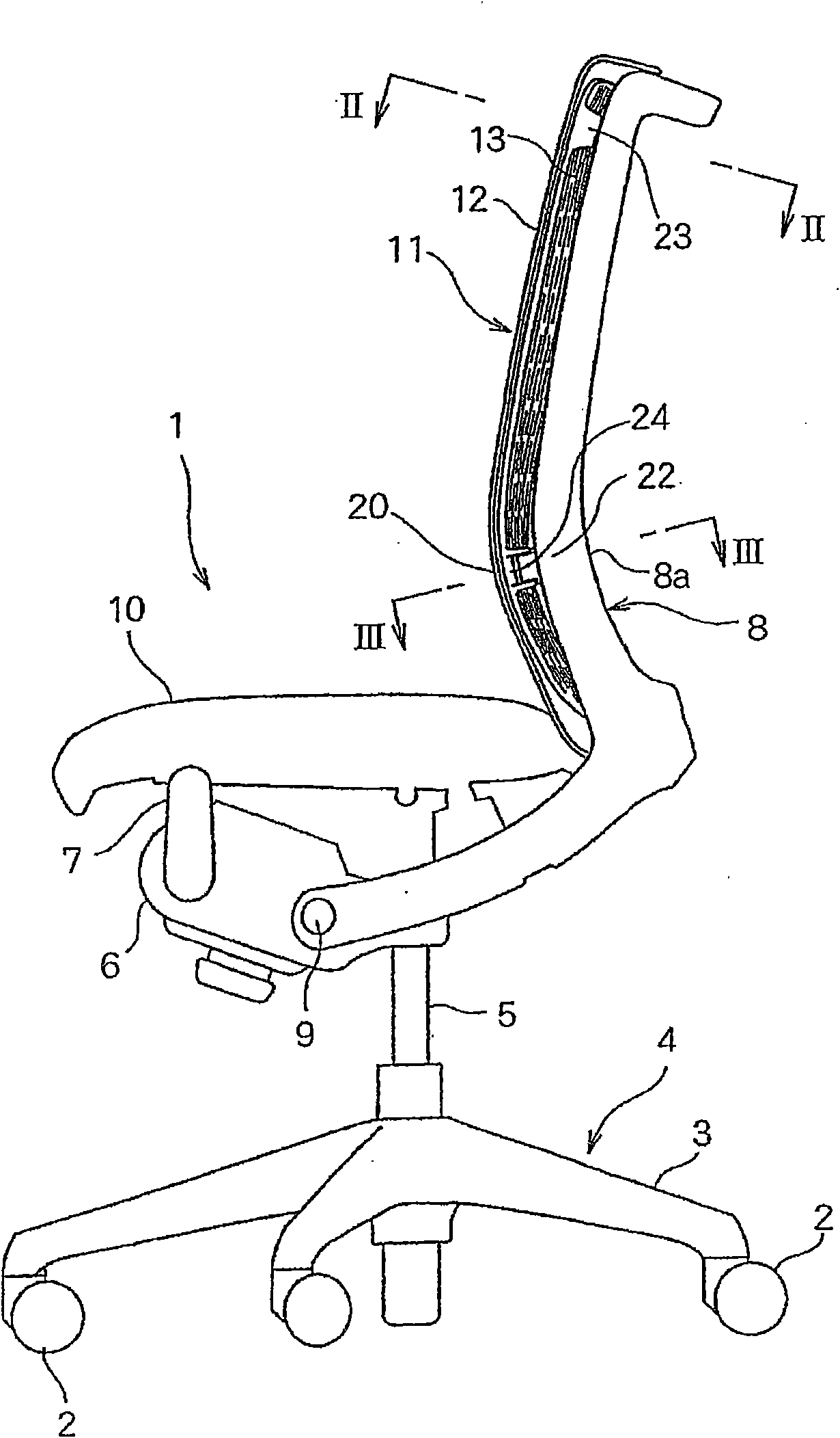
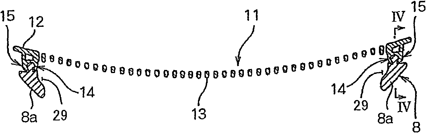
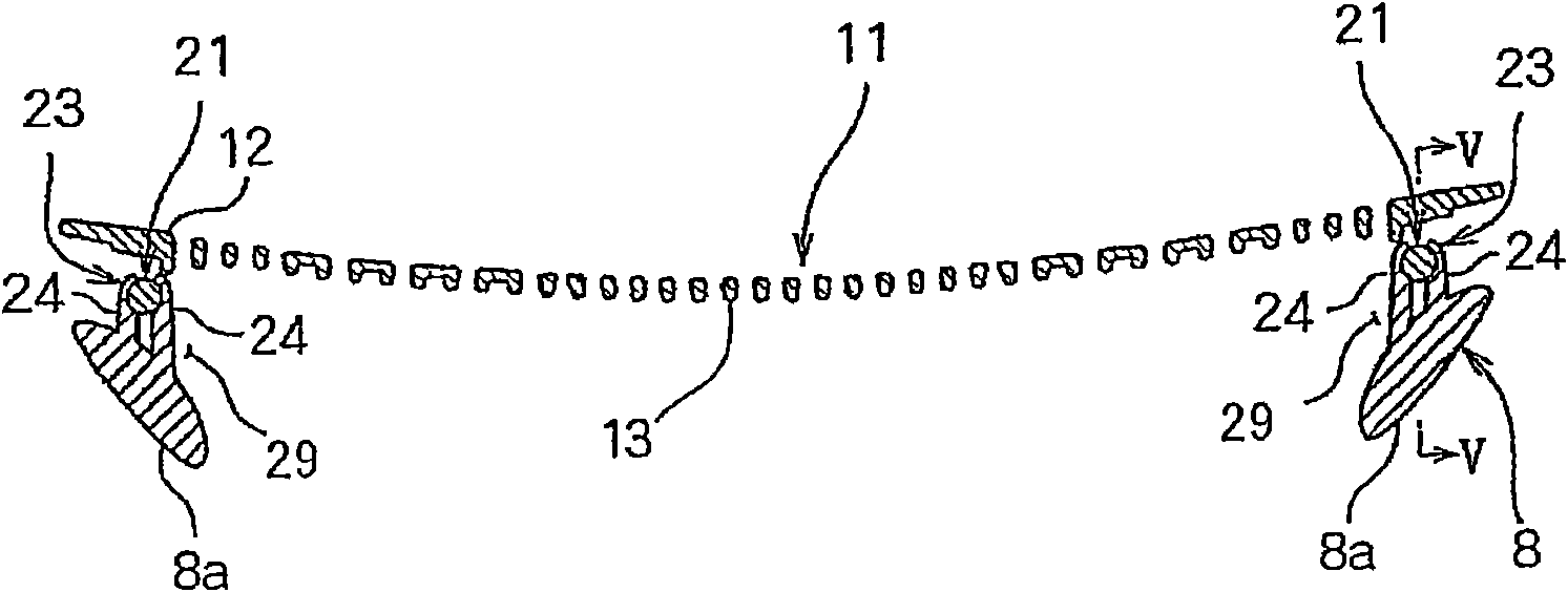
[0023] figure 1 is a side view of a chair including a chair back arrangement according to the present invention. figure 2 is along figure 1 An enlarged horizontal cross-sectional end view cut by line II-II in ; and image 3 is along figure 1 An enlarged horizontal cross-sectional end view of the line III-III cut in .

[0024] The chair 1 comprises a leg unit 4 with five radially extending legs 3 and each leg 3 has a caster 2 at the end; A base 6 at the upper end of the column 5 .

[0025] A seat support frame 7 is mounted to the front end of the base 6 at the lower end. As for the base 6 , the front ends of the side frames 8 a of the back frame 8 are pivotally mounted on pivots 9 . The backrest frame 8 is always urged forwards and downwards by urging means (not shown) in the base 6 .

[0026] The seat 10 is supported at the front end by the seat support fr...


PUM


Abstract

A backrest device for a chair, capable of, without a reduction in its strength and rigidity, effectively bending backward so as to follow the shape of the back of a person seated on the chair, providing the person with excellent sitting comfort. In the backrest device, a back board (11) is supported by a backrest frame, and the back board (11) has a flexible back stopper (13) on the inner side of a back frame (12). The thickness of a vertical intermediate section of the back stopper (13) is gradually increased from both left and right sections of the intermediate section toward the center such that the thickness is less in both left and right sections and is maximum at the center.

Description

technical field [0001] The present invention relates to a backrest arrangement of a chair comprising a flexible back support supporting the back of a seated person in a backrest frame. Background technique [0002] In for example JP2002-125797A, JP2005-160558A (especially attached Figure 10-1 7) and JP2001-128785A disclose such a chair back device. [0003] In the back shells of the backrest devices of JP2002-125797A and JP2005-160558A, a plurality of openings are formed throughout the back shell, which flexes backward when pressed by a person's back. However, the thickness of the back shell is approximately equal, and the entire back shell cannot effectively flex backwards along the shape of the back, so sitting comfort cannot be obtained. [0004] In order to overcome said disadvantages, the back shell can be made thinner for easier flexing, but the strength and rigidity of the back shell is reduced, so that the durability is reduced and the sitting comfort may become le...

Claims


Application Information

Patent Timeline
IPC IPC(8): A47C7/40A47C3/026
CPCA47C31/023
Inventor 益永浩五十岚僚小田洋一郎
Owner OKAMURA MFG CO LTD
Why Eureka
Try Eureka