Curved screen packaging and transporting device with impact-resistant protection function
A transportation device and curved screen technology, applied in the field of curved screens, can solve the problems of increasing the cost of packaging and transportation, the ineffective use of space, and the consumption of shock-absorbing packaging materials, so as to increase stability and impact resistance, reduce usage, and reduce damage effect
- Summary
- Abstract
- Description
- Claims
- Application Information
AI Technical Summary
Problems solved by technology
Method used
Image
Examples
Embodiment 1
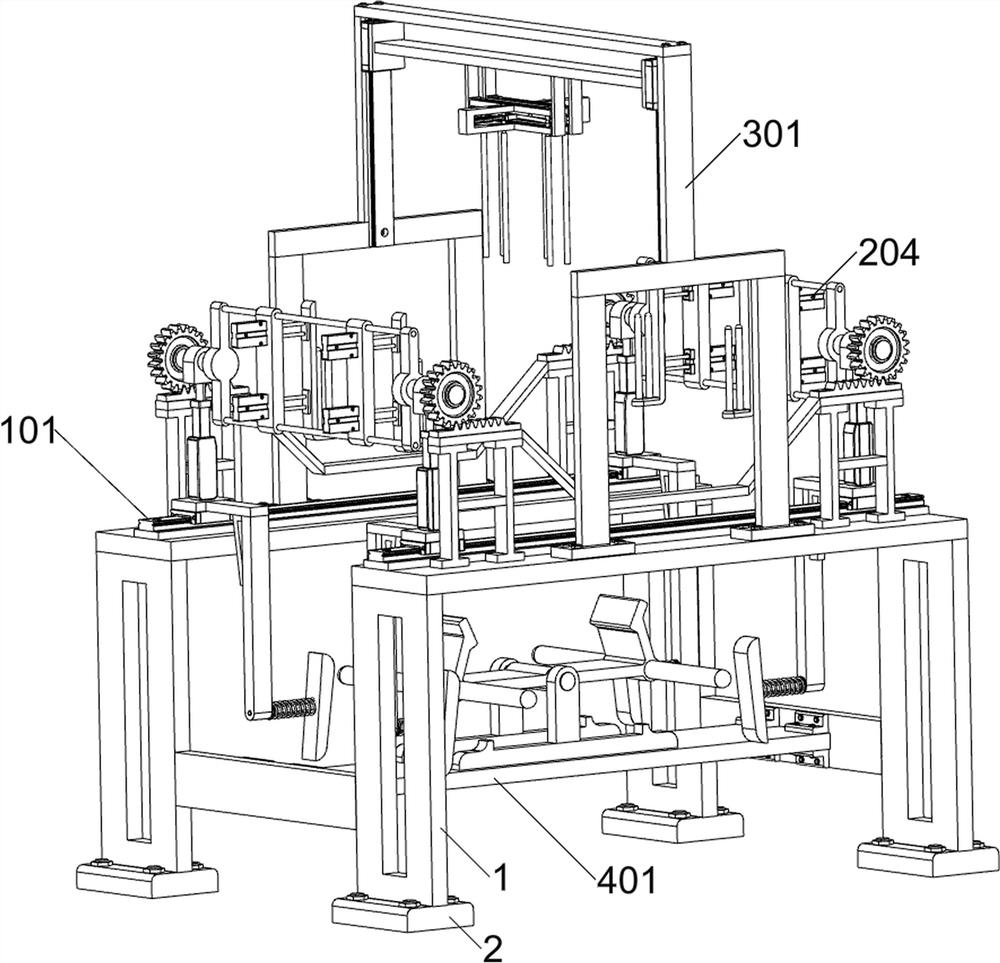
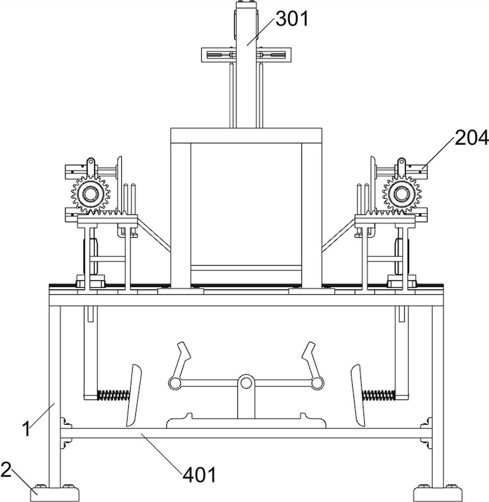
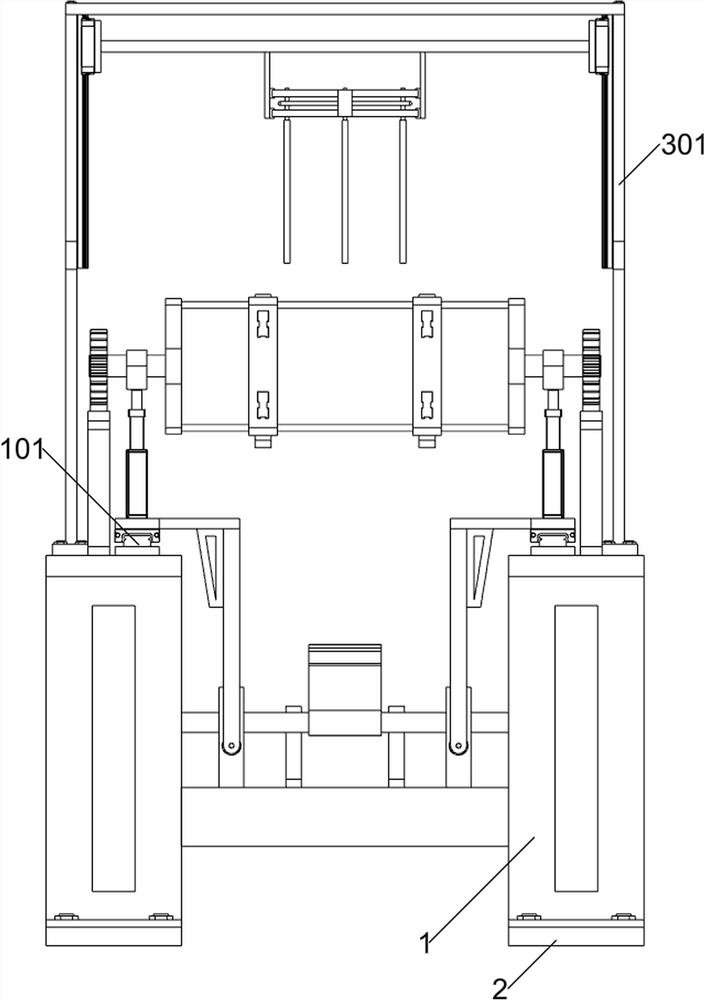
[0034] A curved screen packaging and transportation device with impact protection, according to Figure 1-3 As shown, it includes a bottom frame 1 and an anti-skid pad 2; an anti-skid pad 2 is installed on each of the four feet of the bottom frame 1; it also includes a turning unit, a curved screen clamping unit and an opposite buckle fixing unit; the bottom frame 1 The front part of the upper surface and the rear part of the upper surface are connected with an overturning unit; the front part of the upper surface of the chassis 1 and the rear part of the upper surface are connected with opposing fastening and fixing units, and the overturning unit is located between the opposing buckling and fixing units; the overturning unit The left part and the right part are connected with curved screen clamping units.
[0035] Before using a curved screen packaging and transportation device with anti-shock protection, hereinafter referred to as the packaging device, firstly, the bottom f...
Embodiment 2
[0037] On the basis of Example 1, according to figure 1 with Figure 4-8 As shown, the turning unit includes a first electric slide rail 101, a first mounting plate 102, a first electric actuator 103, an adapter block 104, a first rotating shaft 105, a gear 106, a bracket 107, a rack 108 and a first U Shaped frame 109; Underframe 1 upper surface front part and upper surface rear part respectively are equipped with a first electric slide rail 101; A first mounting plate 102; a first electric actuator 103 is installed on the upper surface of each of the four first mounting plates 102; an adapter block 104 is fixedly connected to the upper ends of the telescopic parts of the four first electric actuators 103; The upper part of the transfer block 104 is rotatably connected with a first rotating shaft 105; the two first rotating shafts 105 on the left on the opposite side of the outer ring surface and the two first rotating shafts 105 on the right on the opposite side of the outer...
Embodiment 3
[0047] On the basis of Example 2, according to figure 1 with Figure 9-10 As shown, it also includes a limiting unit, the lower part of the chassis 1 is connected to the limiting unit; the two first mounting plates 102 in the front and the two first mounting plates 102 in the rear are connected to the limiting unit on the opposite side; the limiting unit includes a horizontal plate 401, a second T-shaped plate 402, a second rotating shaft 403, a U-shaped plate 404, a cross bar 405, a second L-shaped plate 406, a second elastic member 407 and a push plate 408; the lower part of the chassis 1 is bolted to a horizontal plate 401 A second T-shaped plate 402 is respectively welded on the front part of the upper surface of the horizontal plate 401 and the rear part of the upper surface; the upper part of the two second T-shaped plates 402 is rotatably connected with a second rotating shaft 403; the middle part of the outer surface of the second rotating shaft 403 is fixed There is ...
PUM
 Abstract
Description
Claims
Application Information
 - R&D
- Intellectual Property
- Life Sciences
- Materials
- Tech Scout
- Unparalleled Data Quality
- Higher Quality Content
- 60% Fewer Hallucinations
Browse by: Latest US Patents, China's latest patents, Technical Efficacy Thesaurus, Application Domain, Technology Topic, Popular Technical Reports.
© 2025 PatSnap. All rights reserved.Legal|Privacy policy|Modern Slavery Act Transparency Statement|Sitemap|About US| Contact US: help@patsnap.com


