Ice removal system

A technology for deicing systems and equipment, applied in the field of aerospace anti-icing systems, can solve problems such as power consumption and the complexity of electric heating systems, and achieve the effects of reducing manufacturing costs, saving weight and space, and avoiding surface deformation/fluctuation

Pending Publication Date: 2020-12-08
GKN AEROSPACE SERVICES LTD
View PDF0 Cites 0 Cited by
  • Summary
  • Abstract
  • Description
  • Claims
  • Application Information

AI Technical Summary

Problems solved by technology

[0005] However, the disadvantage of an electric heating system is its complexity and power consumption, which must be fed from a generator in the engine

Method used


Image

  • Ice removal system
  • Ice removal system
  • Ice removal system

Examples


Embodiment Construction

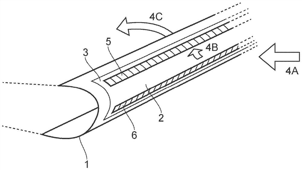
[0122] figure 1 One application for the invention disclosed herein is shown on the leading edge of an aircraft wing 1 .

[0123] The wing 1 comprises a leading edge 2 which is a curved profile forming the front or upstream part of the wing. The airfoil generates lift by splitting the airflow into two streams on the upper and lower surfaces of the airfoil.

[0124] Extending from the top and bottom surfaces of the leading edge 1 is an aft region 3 or region extending from the leading edge away from the front of the wing towards the trailing edge (not shown at the rear of the wing). exist figure 1 Only a section of the wing is shown in FIG. 2 , but it will be appreciated that the wing extends from the fuselage of the aircraft to the wing tip.

[0125] Arrows 4A, 4B and 4C show the air flow over the surface. As the aircraft is pushed through the air, the air 4A approaches the wing leading edge 2 and collides or collides with the surface. As indicated by arrow 4B, the air is ...


PUM


Abstract

An ice removal apparatus for an aircraft comprising a laminate structure encapsulated an electrically operable heater. The laminate structure comprises a plurality of layers and at least two layers are configured to be selectively movable relative to each other to increase the separation of the two layers.

Description

technical field [0001] The present invention relates to aerospace anti-icing systems, and in particular, but not exclusively, to an anti-icing system capable of use with small to medium aircraft as well as large commercial aircraft. Background technique [0002] Aerospace surfaces such as wing leading edges or engine nacelles (etc.) are prone to ice accretion during flight because the cold outer surfaces of the components come into contact with water during flight, landing, taxiing or takeoff. [0003] Icing may alter the aerodynamic profile or shape of a component, thereby altering the function of the component. This could have disastrous consequences. In the engine nacelle, ice can be re-ingested into the engine, which can have very serious and dangerous consequences. [0004] In order to solve these problems, a number of heating systems have been employed in different aircraft. One system involves the use of hot exhaust from an engine that can be directed to a desired ...

Claims


Application Information

Patent Timeline
Patent Type & Authority Applications(China)
IPC IPC(8): B64D15/12B64D15/16B64D15/08
CPCB64D15/08B64D15/12B64D15/163B64D15/16B32B27/08B32B27/288B32B2250/05B32B2250/24B32B2307/206B32B2307/30B32B2605/18H05B3/36H05B2203/005H05B2203/016
Inventor 斯蒂芬·古德费洛-琼斯阿什利·布鲁克斯
Owner GKN AEROSPACE SERVICES LTD
Why Eureka
Try Eureka