Hinged fitting

A technology of assembly and articulation, applied in the direction of transmission, vehicle parts, transportation and packaging, etc.

Inactive Publication Date: 2009-11-11
汉斯·沃纳·沃斯
View PDF3 Cites 2 Cited by
  • Summary
  • Abstract
  • Description
  • Claims
  • Application Information

AI Technical Summary

Problems solved by technology

However, in the event of extremely high forces acting on the pivotable fitting part, as may occur during sharp deceleration of the vehicle, the frictional connection between the outer and inner wedges is overcome, so the Pivotable parts are unintentionally adjusted

Method used


Image

  • Hinged fitting
  • Hinged fitting

Examples


Embodiment Construction

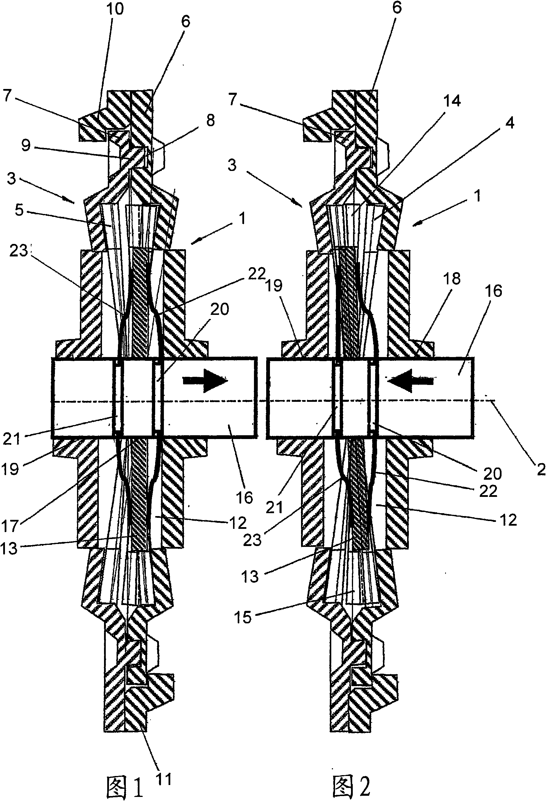
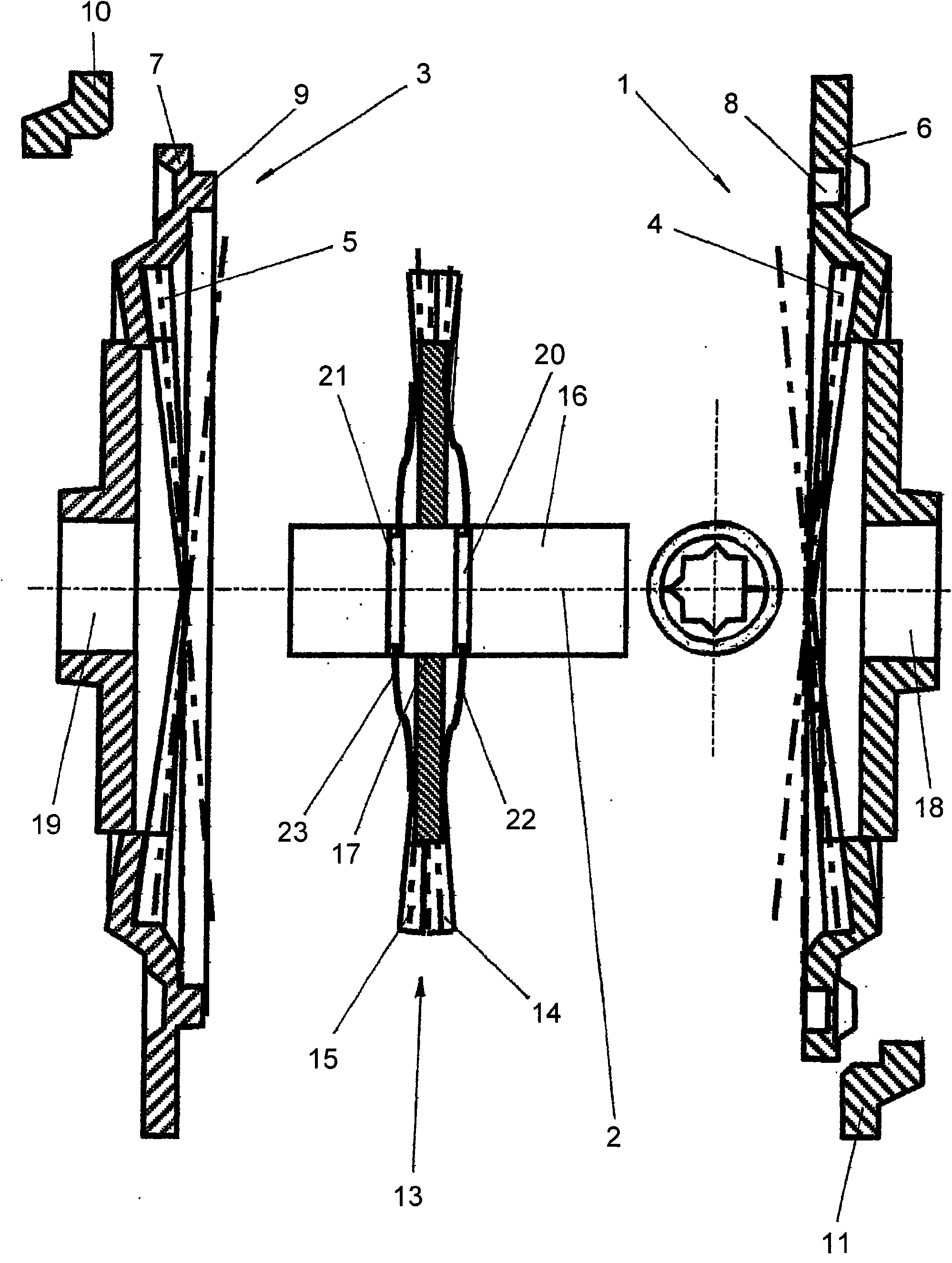
[0055] The articulated fitting shown in these figures has a first gear 1 integrally formed with a fixed fitting part; and a pivotable fitting part capable of pivoting about a The axis 2 pivots relative to the fixed fitting part and is integral with a second gear 3 .

[0056] The first gear 1 has an axially oriented toothing 4 and the second gear 3 has a likewise axially oriented toothing 5 , the two toothings 4 and 5 are axially opposite each other and face each other, and preferably The tooth shape is designed as a helical gear.

[0057] The gearwheel 1 and the gearwheel 3 abut against each other and face each other with their annular regions 6 and 7 located radially outside the tooth profile 4 and the tooth profile 5 . In this case, an annular groove 8 is formed in the annular region 6 of the first gear 1 , which is open towards the annular region 7 of the second gear 3 , concentric with respect to the pivot axis 2 , and in which An axially protruding annular lug 9 of the ...


PUM


Abstract

The invention relates to a hinged fitting for vehicle seats, having a fixed fitting part and a pivotable fitting part which are pivotably connected to each other about a swivel axis (2). The swivel movement of the pivotable component can be blocked in a stepless manner by a blocking device. A first blocking element (4) is connected in a nonrotatable manner to the fixed fitting part, and a second blocking element (5) is connected in a nonrotatable manner to the pivotable fitting part. Thereby the blocking elements which are positioned opposite each other coaxially to the swivel axis (2) can be coupled and decoupled to and from each other in a nonrotable manner by means of an actuating unit.

Description

technical field [0001] The present invention relates to a hinged assembly for a vehicle seat having a fixed assembly part and a pivotable assembly part connected to each other in such a way that they can pivot about a pivot axis. pivoting, wherein the pivotal movement of the pivotable assembly part can be infinitely variable prevented by a blocking device with a first blocking element and a second blocking element, the first blocking element with a is connected to the fixed mounting part in a rotationally fixed manner, and the second blocking element is connected to the pivoting mounting part in a rotationally fixed manner, wherein relative to the pivot The blocking elements, whose axes lie coaxially opposite one another, can be connected to one another in a rotationally fixed manner and can be separated from one another by an actuating device. Background technique [0002] In the case of hinged fittings of this type, it is known to fixedly arrange an external wedge on a fi...

Claims


Application Information

Patent Timeline
Patent Type & Authority Applications(China)
IPC IPC(8): B60N2/225B60N2/44F16H1/32B60N2/90
CPCB60N2/2254B60N2/2252B60N2/444F16H1/321B60N2/938
Inventor 汉斯·沃纳·沃斯
Owner 汉斯·沃纳·沃斯
Why Eureka
Try Eureka