Container underframe

A container and underframe technology, which is applied in the field of container underframe structure, can solve the problems of inconsistent external dimensions and inability to carry out intermodal transport of container ships, and achieve the effects of reducing dead weight, improving loading efficiency, and increasing internal height

Active Publication Date: 2012-07-25
SHENGSHI CONTAINER MANAGEMENT SHANGHAI
View PDF0 Cites 0 Cited by
  • Summary
  • Abstract
  • Description
  • Claims
  • Application Information

AI Technical Summary

Problems solved by technology

[0005] At this stage, due to the frequent international trade, the volume of container transportation has increased sharply. People use some methods to increase the transportation efficiency of containers. The most intuitive way to increase the transportation efficiency of containers is to increase the space inside the container. To load more goods, some ultra-wide and ultra-long containers used in Europe and the United States have a larger internal space than ordinary containers and a relatively large amount of cargo. However, their external dimensions do not meet the requirements of the ISO standard and cannot be used for container ships. intermodal

Method used


Image

  • Container underframe
  • Container underframe
  • Container underframe

Examples


Embodiment 1

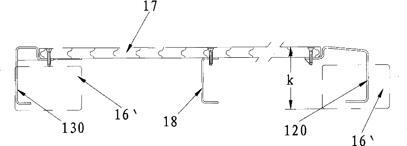
[0034] Such as Figure 4 , 5 The illustrated container underframe 3 includes bottom side beams 300 on both sides of the bottom frame, door sills 301 and front end lower beams 302 at both ends of the underframe, a plurality of parallel and arranged side by side between the door sill 301 and the front end lower beam 302 The bottom cross beam 303 is welded with bottom corner pieces 361 at both ends of the door sill 301 and both ends of the front lower beam 302; the aforementioned bottom side beam 300, bottom cross beam 303, door sill 301, and front end lower beam 302 are welded and connected to form a frame body, The wooden floor 37 is laid on the frame body, and its middle part is supported on the top surface of the bottom beam 303. The inner end of the door sill 301 is provided with a sill bending section 3011 that is downward and whose upper surface is flush with the top surface of the bottom beam 303 for carrying the wooden floor 37. Correspondingly, in order to ensure the flat...

Embodiment 2

[0040] In order to increase the inner height of the container more effectively, reduce the height of the bottom frame of the container, such as Figure 8 , 9 As shown, a recess 3611 is provided on the matching part of the bottom corner piece 361 for overlapping with the wooden floor 37, and the end corner of the wooden floor 37 can be placed in the recess 3611. The depth of the recess 3611 is the same as that of the wooden floor 37. The thickness is the same, so that the upper surface of the wooden floor 37 is flush with the upper surface of the bottom corner piece 361. Here, the purpose of opening the recess 3611 on the bottom corner piece is to maintain the structural integrity of the wooden floor 37. From the perspective of achieving the purpose of supporting the bottom corner piece 361 on the wooden floor 37, such as Picture 10 In the manner shown, a support platform 3612 for supporting the wooden floor is provided on the periphery of the inner side of the bottom corner pie...


PUM


Abstract

The invention relates to a container underframe comprising a doorsill, a frontend underbeam, a plurality of bottom cross beams, a floor and ISO standard bottom corner fittings, wherein the doorsill and the frontend underbeam are respectively positioned at both ends of the underframe and are mutually parallel; the bottom cross beams are positioned between the doorsill and the frontend underbeam andare parallel to the doorsill and the frontend underbeam; the floor is laid on the top of the underframe; the ISO standard bottom corner fittings are positioned at the four end corner bottoms of the underframe and are connected to the ends of the doorsill and the frontend underbeam; the floor is overlapped on the doorsill, the frontend underbeam and the bottom cross beams; the upper planes of thecontacting parts of the doorsill and the frontend underbeam with the floor are aligned with the upper planes of the bottom corner fittings; and the four end corners of the floor are overlapped on theupper planes of the four bottom corner fittings. By reducing the height of the doorsill, the frontend underbeam and the bottom cross beams, the upper planes of the doorsill, the frontend underbeam andthe bottom cross beams can be aligned with the upper planes of the bottom corner fittings, and the four end corners of the floor are overlapped on the upper planes of the bottom corner fittings, so as to increase the interior height of a container.

Description

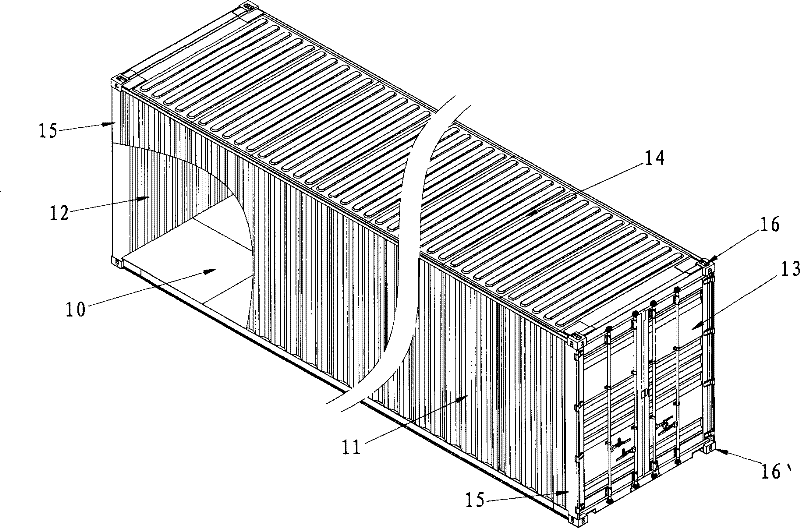
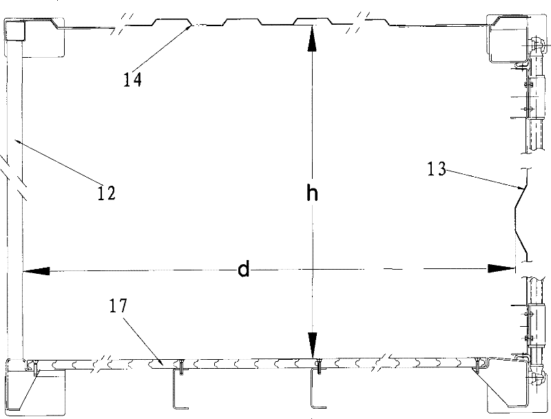
Technical field [0001] The invention relates to components of large containers, in particular to an underframe structure of the container. Background technique [0002] As the main tool of international combined transportation, container has been used for more than 50 years since 1956 and has been widely used. With the continuous strengthening of international trade, container transportation has become the main means of international combined transportation. [0003] At present, the overall configuration of general-purpose containers is a hexahedron. In terms of specific structures, such as figure 1 As shown, they generally include an underframe platform 10 at the bottom of the box body, a front wall 12 and a box door 13 respectively located at the two ends of the underframe platform 10, and side walls 11 on both sides of the box body, located on the top of the box body. The top plate 14 is located at the junction of the side wall 11 and the front wall 12 and the box door 13, the c...

Claims


Application Information

Patent Timeline
Patent Type & Authority Patents(China)
IPC IPC(8): B65D90/02B65D88/12
Inventor 袁洪伟陈健昭潘家和
Owner SHENGSHI CONTAINER MANAGEMENT SHANGHAI
Why Eureka
Try Eureka