Beating device

A technology of applying device and driving device, which is applied in transportation and packaging, printing, rotary printing machines, etc., and can solve problems such as belt tension weakening

Active Publication Date: 2009-12-02
海德堡印刷机械知识产权股份两合公司
View PDF1 Cites 13 Cited by
  • Summary
  • Abstract
  • Description
  • Claims
  • Application Information

AI Technical Summary

Problems solved by technology

Furthermore, when the channel is in the region of the transfer gap, the usual weakening of the belt tension occurs on both sides

Method used


Image

  • Beating device
  • Beating device
  • Beating device

Examples


Embodiment Construction

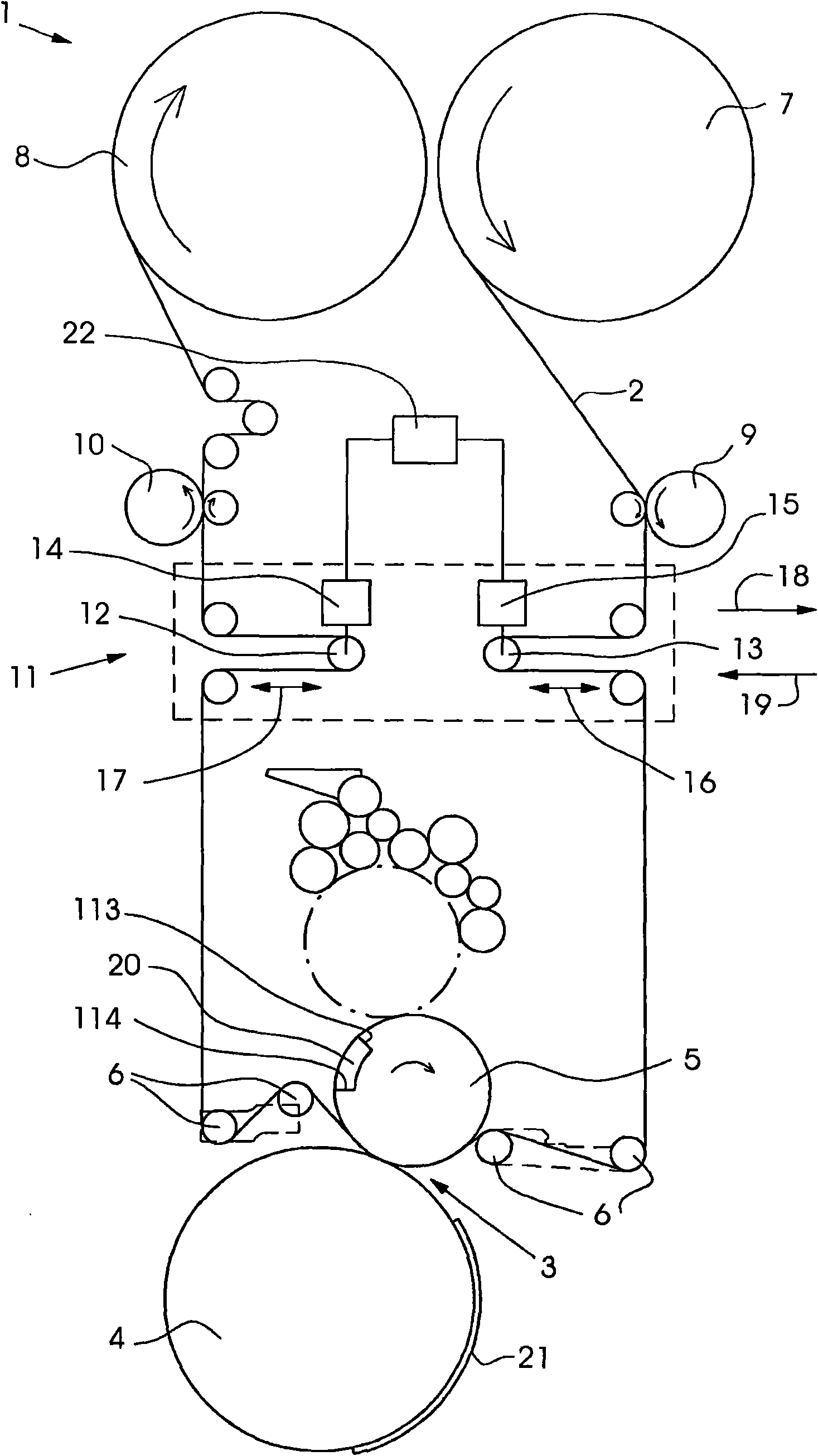
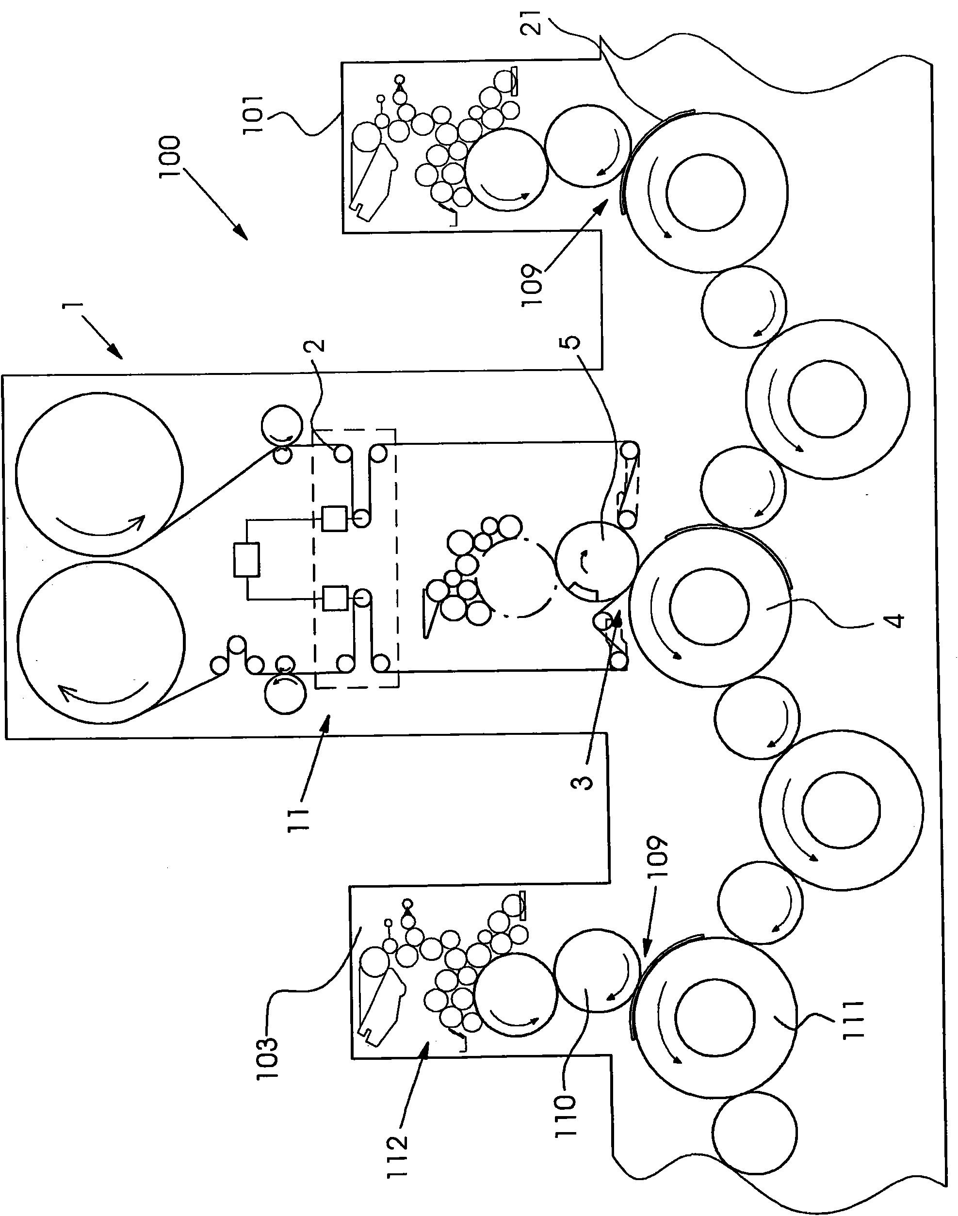
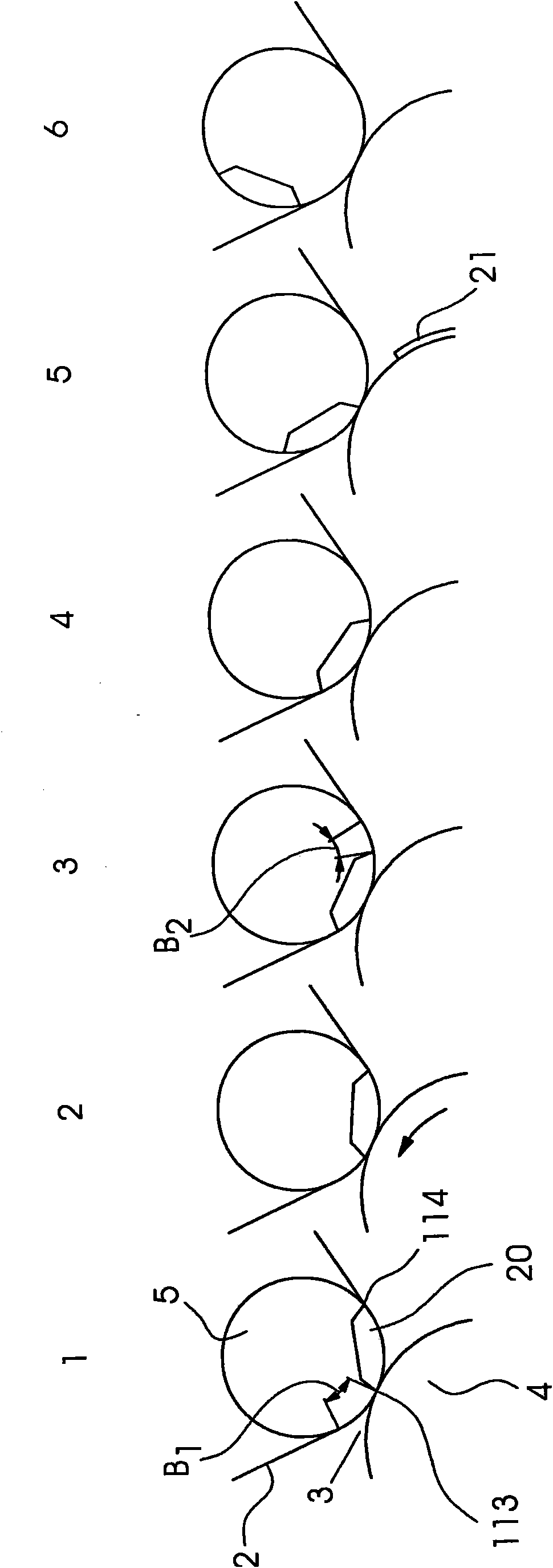
[0035] figure 1 shows a film transfer device 1 in which a transfer film 2 is guided through a transfer nip 3 .

[0036] The transfer gap 3 is formed by a transfer roller 5 and a counter-pressure roller 4 . The transfer film 2 is unwound from the supply roll 7 and pulled by a front puller 9 in the direction of the transfer nip 3 . The supply roll 7 rests on a friction shaft (not shown here) and is driven at a speed that is lower than the speed of the printing material 21 . The drive of the supply roll 7 takes place via a friction shaft. The transfer film 2 is pulled off the supply roll 7 via the front drawer 9 , the rollers of the front drawer 9 being driven at a speed higher than the friction shaft speed of the supply roll 7 . However, the front drawer 9 always works at a speed that is lower than the speed of the printing material 21 .

[0037] The unwound transfer film 2 is guided through the transfer nip 3 by the front float device 13 of the clock module 11 and by the fu...


PUM


Abstract

The present invention relates to a method and an apparatus for reducing web tension change during beating of a transfer film (2) in a film transfer device (1), include severely impairing the web tension (204, 205) by contact sections before and after a transfer nip (3) of the film transfer device (1) as the transfer film (2) runs through a channel (20) at the transfer nip (3). In order to reduce the web tension changes, front and/or rear guide elements before and after the transfer nip (3) are moved time-asynchronously in relation to one other in order to at least reduce web tension fluctuations of the transfer film (2) as it passes through the transfer nip (3).

Description

technical field [0001] The invention relates to a method and a device for transferring a transfer layer attached to a carrier film by means of a separating layer under pressure to a flat material at least partially coated with an adhesive material. Background technique [0002] Film transfer devices of the described type are used in the finishing of printed products, for example in order to produce gloss effects. This machine can be divided into hot embossing film machine and cold film embossing machine. In cold film embossing presses, the transfer layer is transferred only under pressure, but not additionally under the action of heat, to the flat material, ie to the printing substrate such as a sheet. Usually, in a cold film transfer device, ie a cold film embossing device, with a printing device supported in front of the transfer device, the adhesive material is printed on, whereby a printed image consisting of the adhesive material remains on the sheet, the printed With...

Claims


Application Information

Patent Timeline
Patent Type & Authority Applications(China)
IPC IPC(8): B41F16/00B41F19/06
CPCB41F33/06B65H37/002B41F13/02B41F16/00
Inventor M·尤尔克维茨S·迈尔J·劳特尔特J·松嫩沙因A·韦伯
Owner 海德堡印刷机械知识产权股份两合公司
Why Eureka
Try Eureka