Spacial multi-angle truss structure

A truss structure and multi-angle technology, applied in the field of truss structures, can solve the problem that the truss connection nodes cannot adapt to the change of the connection angle of the truss rods

Inactive Publication Date: 2009-12-02
北京华洋建设开发有限公司
View PDF4 Cites 4 Cited by
  • Summary
  • Abstract
  • Description
  • Claims
  • Application Information

AI Technical Summary

Problems solved by technology

[0003] In order to overcome the deficiencies of the prior art, the present invention provides a space multi-angle truss structure to solve the technical problem that the truss connection nodes cannot adapt to the change of the connection angle of the truss rods

Method used


Image

  • Spacial multi-angle truss structure
  • Spacial multi-angle truss structure
  • Spacial multi-angle truss structure

Examples


Embodiment Construction

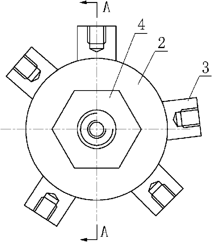
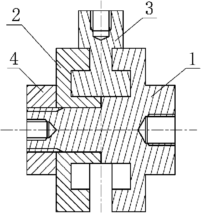
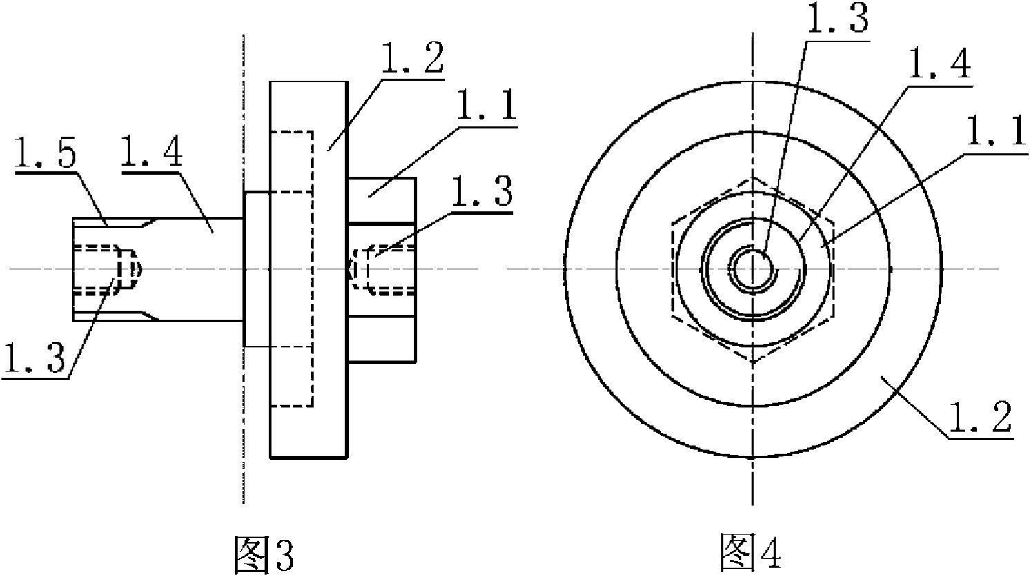
[0035] Referring to the embodiment shown in Figure 1417, this space multi-angle truss structure is composed of truss rods 5, space bolt ball nodes 6 and multi-angle variable nodes 7. see Figure 1-5 , the multi-angle variable node is composed of bushing 1, sliding bushing 2, slider 3 and nut 4. The center of bushing 1 is in the shape of a stepped shaft, and the two ends of the stepped shaft are respectively provided with concentric joints that can be connected with truss rods. Screw hole 1.3, the high-order shaft 1.1 of the stepped shaft extends a disc-shaped bushing chute 1.2, and the end of the low-order shaft 1.4 of the stepped shaft has an external thread 1.5. The center of the shaft sleeve 1 is in the shape of a three-stage or two-stage stepped shaft 1.1.

[0036] see figure 1 , figure 2 , Figure 68, the sliding sleeve 2 is set on the lower shaft 1.4 of the stepped shaft and fixed by the nut 4, the inner diameter of the sliding sleeve 2.1 is adapted to the outer diame...


PUM


Abstract

The utility model relates to a spacial multi-angle truss structure, which consists of a truss rod, spacial bolt ball nodes and multi-angle variable nodes. The multi-angle variable nodes are formed by a shaft sleeve, a sliding sleeve, a sliding block and a nut; the center of the shaft sleeve is of a stepped shaft shape; two ends of the stepped shaft are respectively provided with concentric screw holes which can be connected with the truss rod; a disk-shaped sliding chute of the shaft sleeve extends out of a high-step shaft of the stepped shaft; the sliding sleeve is sleeved on a low-step shaft of the stepped shaft and fixed by nuts; the inside aperture of the sliding sleeve is matched with the outside diameter of the low-step shaft of the stepped shaft; a dished sliding chute of the sliding sleeve extends out of the outer edge of the sliding sleeve; the sliding chute of the sliding sleeve and the sliding chute of the shaft sleeve are oppositely and symmetrically arranged so as to form an annular groove with a large web and a small opening; the inner end of the sliding block is provided with a clamping head embedded into the annular groove, while the outer end is provided with a connector of the truss rod; and the outer end and the inner end are connected into a whole through a neck. The truss structure can adapt to the change of a slope; the angles of the multi-angle variable nodes are free, flexible and adjustable; and the spacial multi-angle truss structure is convenient to mount, attractive in appearance ad more flexible in use compared with the conventional bolt ball.

Description

technical field [0001] The invention relates to a truss structure. Background technique [0002] In the traditional three-dimensional truss structure, the truss rods are connected by bolt ball joints, and the positions of the bolt ball holes on the bolt ball joints are fixed, so the space bolt ball three-dimensional truss structure cannot change its connection angle. When the slope changes or the shell changes, it is often unable to adapt to the slope and angle changes, thereby reducing the adaptability of the engineering mechanism and equipment, causing a lot of inconvenience. Contents of the invention [0003] In order to overcome the deficiencies of the prior art, the present invention provides a space multi-angle truss structure to solve the technical problem that the connection nodes of the truss cannot adapt to the change of the connection angle of the truss rods. [0004] The technical solution adopted by the present invention to solve its technical problems is: ...

Claims


Application Information

Patent Timeline
Patent Type & Authority Applications(China)
IPC IPC(8): F16S3/08E02D17/00E01C19/48
Inventor 杨永革翟利川
Owner 北京华洋建设开发有限公司
Why Eureka
Try Eureka