Supercharge Your Innovation With Domain-Expert AI Agents!

Frock clamp

A technology of tooling fixtures and clamping blocks, which is applied in the field of tooling fixtures, can solve problems such as low efficiency, inconvenient work efficiency, and complicated operation of tooling fixtures, and achieve the effect of simple actions and high work efficiency

Inactive Publication Date: 2009-12-16
OCEANS KING LIGHTING SCI&TECH CO LTD
View PDF0 Cites 35 Cited by
  • Summary
  • Abstract
  • Description
  • Claims
  • Application Information

AI Technical Summary

Problems solved by technology

[0003] The technical problem to be solved by the present invention is to provide a tooling fixture with simple, quick and efficient operation in view of the problems of complicated operation, inconvenient operation and low work efficiency of the tooling fixture in the prior art

Method used


Image

  • Frock clamp
  • Frock clamp
  • Frock clamp

Examples


Embodiment Construction

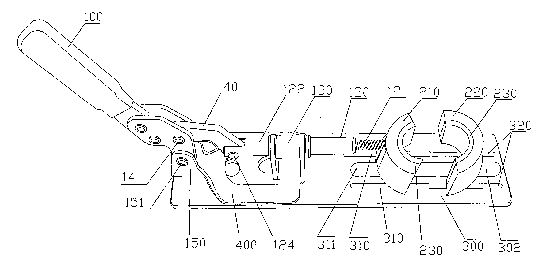
[0020] Figure 1 to Figure 4 A preferred embodiment of the present invention is shown.

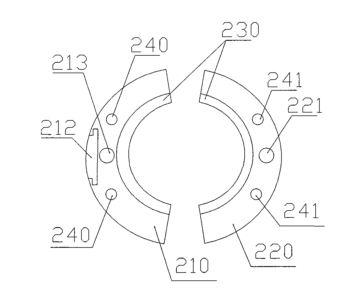
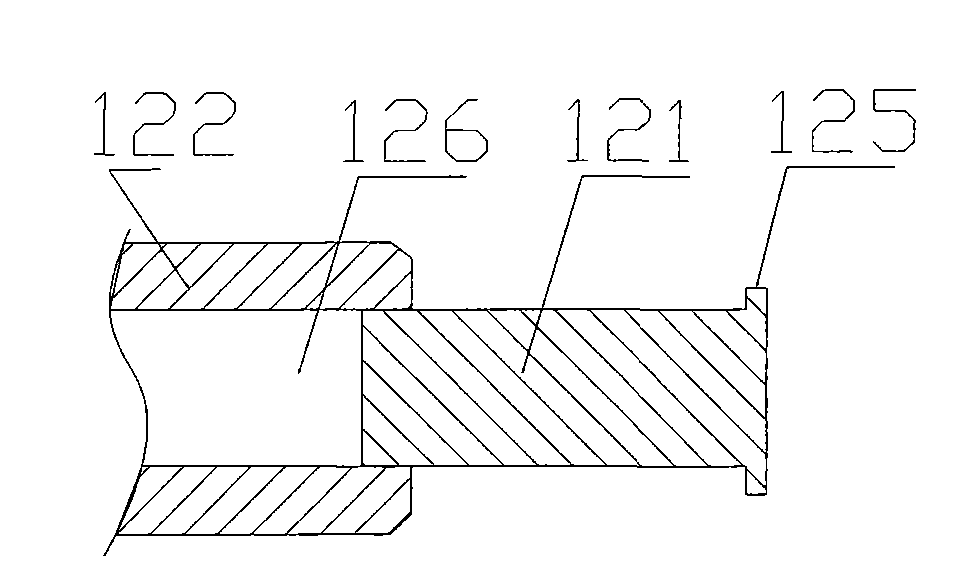
[0021] A tooling fixture, such as figure 1 As shown, it includes a base plate 300, a first clamping block 220 fixed on the base plate 300, a second clamping block 210 slidably arranged on the base plate 300, and driving the second clamping block to face the first clamping block on the base plate. A mobile driving device. The driving device includes a bracket 400, a driving rod, a pressing rod 100, and a connecting rod 140. The bracket 400 is fixedly installed on the base plate 300 and includes a driving rod support 130 for installing the driving rod and a supporting rod. The two parts of the fixed support 150 connecting the tooth rod; one end of the pressure rod 100 is the rotating connection end, at which end is rotatably connected to the fixed support 150 through the first rotating shaft 151, and the other end is the hand-held end; the drive rod 120 is installed on the drive rod The bracket...


PUM


Abstract

The invention relates to a frock clamp comprising a base plate, a first clamping block, a second clamping block and a driving device, wherein the first clamping block is fixed on the base plate; the second clamping block is arranged on the base plate in a sliding way; the driving device drives the second clamping block and comprises a support frame, a drive rod, a press rod and a connecting rod, wherein one end of the press rod is rotationally connected with a support seat fixed on the base plate through a first rotating shaft, and the other end of the same is a hand-hold end; the drive rod is arranged on the support frame and can move on the support frame along a shaft line of the support frame, one end of the drive rod is connected with the second clamping block, and the other end of the drive rod is rotationally connected to one end of the connecting rod through a second rotating shaft; the other end of the connecting rod is rotationally connected with the press rod through a third rotating shaft; and when the press rod downwards presses, the third rotating shaft passes a connecting line between position points of the first rotating shaft and the second rotating shaft and is positioned at a self-locking state point below the connecting line. The frock clamp has simple workpiece clamping action and high efficiency.

Description

Technical field [0001] The invention relates to a fixture, and more specifically, to a tooling fixture. Background technique [0002] Tooling fixtures are often used to clamp a certain part or product to facilitate the assembly or fastening of the product. Most of the current tooling fixtures have two clamping blocks, and the two clamping blocks are usually driven by a screw rod to adjust the distance between the two clamping blocks to achieve clamping of the objects located between the two clamping blocks. During the use of this kind of tooling fixture, the screw must be rotated when clamping the object, resulting in complex clamping operations, especially when frequent clamping and unclamping operations are performed, resulting in low work efficiency. Summary of the invention [0003] The technical problem to be solved by the present invention is to provide a tooling fixture with simple, quick and high-efficiency operation in view of the complicated, inconvenient and low worki...

Claims


Application Information

Patent Timeline
Patent Type & Authority Applications(China)
IPC IPC(8): B25B5/02B25B5/12B25B5/16
Inventor 周明杰
Owner OCEANS KING LIGHTING SCI&TECH CO LTD
Features
  • R&D
  • Intellectual Property
  • Life Sciences
  • Materials
  • Tech Scout
  • Unparalleled Data Quality
  • Higher Quality Content
  • 60% Fewer Hallucinations
Learn More