Ice-melting method of transmission line with ends therefore infused with reactive current

A technology for power transmission lines and ice-melting methods, applied in reactive power compensation, cable installation, reactive power adjustment/elimination/compensation, etc., can solve the problems of large-capacity adjustable inductors without molding equipment and large investment in equipment, and achieve Facilitate development and implementation, good economic benefits, clear division of responsibilities

Active Publication Date: 2011-04-13
JIXI ELECTRIC POWER BUREAU +1
View PDF0 Cites 1 Cited by
  • Summary
  • Abstract
  • Description
  • Claims
  • Application Information

AI Technical Summary

Problems solved by technology

[0008] The purpose of the present invention is to solve the problem of large-capacity adjustable inductance without molding equipment and large equipment investment in the method of using capacitance compensation and inductance to adjust the negative ice melting method, and provides a transmission line ice melting method that injects reactive current at the end of the line

Method used


Image

  • Ice-melting method of transmission line with ends therefore infused with reactive current
  • Ice-melting method of transmission line with ends therefore infused with reactive current
  • Ice-melting method of transmission line with ends therefore infused with reactive current

Examples


specific Embodiment approach 1

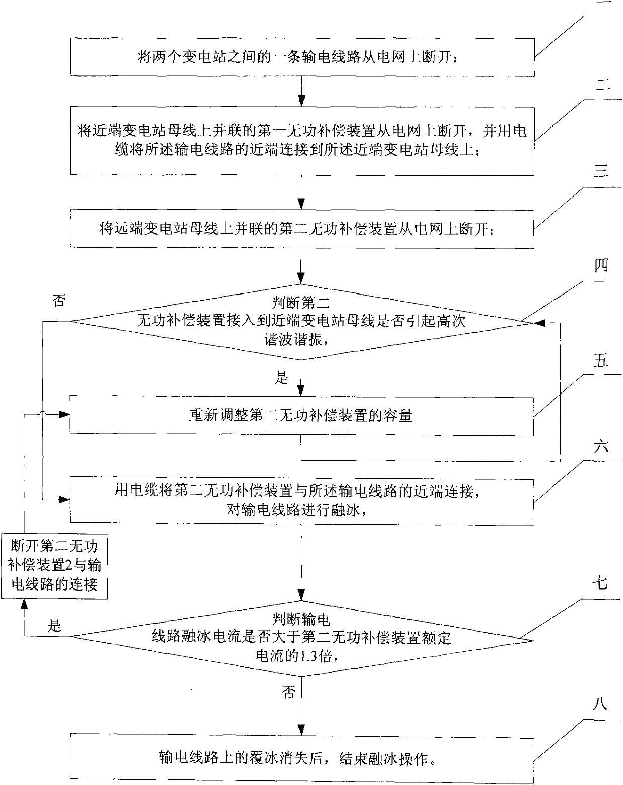
[0027] Specific implementation mode one: the following combination Figure 1 to Figure 5 Describe this embodiment, the method of this embodiment includes the following steps:

[0028] Step 1. Disconnecting a transmission line between two substations from the grid;

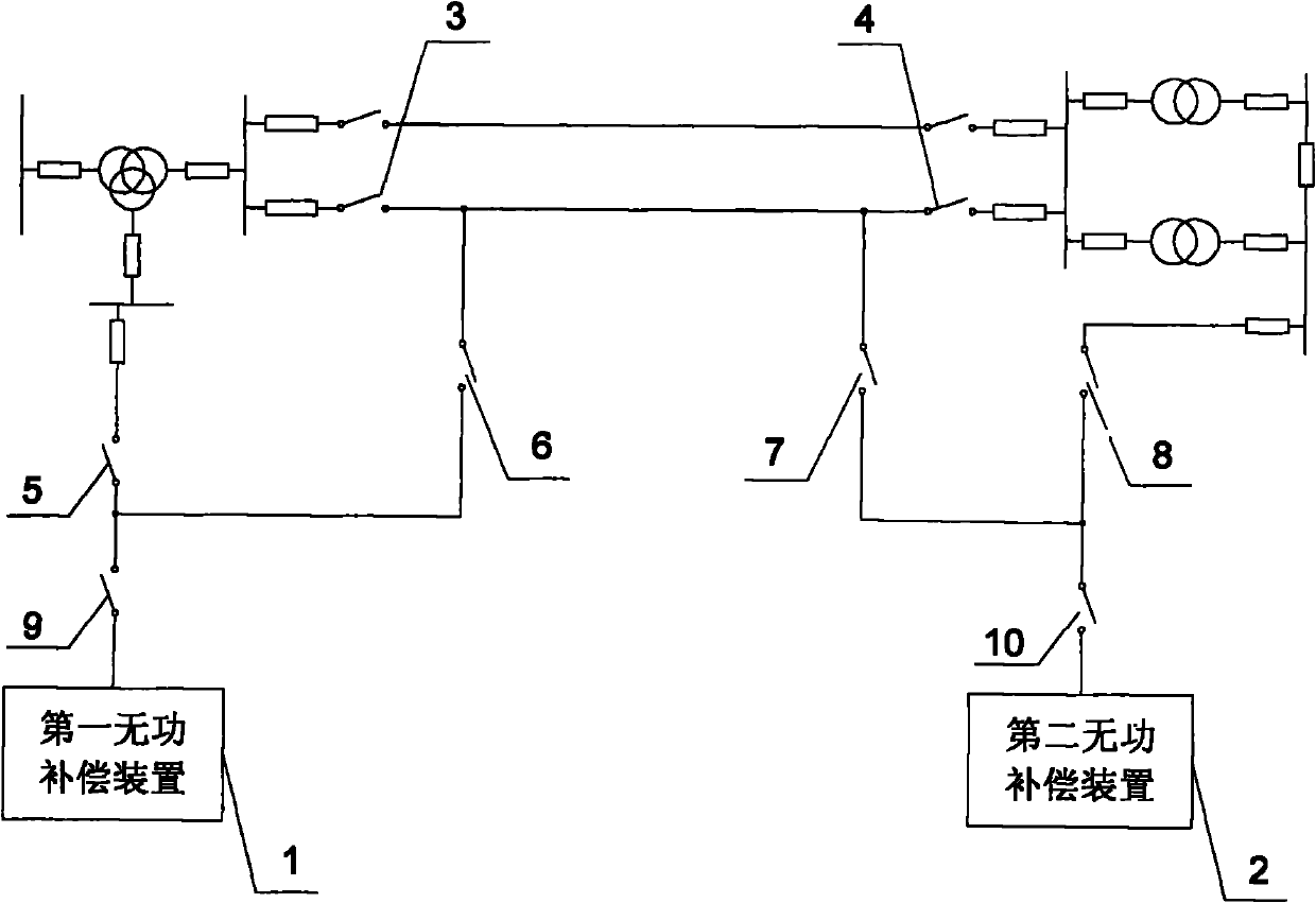
[0029] Step 2, disconnect the first reactive power compensation device 1 connected in parallel on the bus of the near-end substation from the grid, and connect the near-end of the transmission line to the bus of the near-end substation with a cable;

[0030] Step 3, disconnecting the second reactive power compensation device 2 connected in parallel on the remote substation busbar from the power grid;

[0031] Step 4, judging whether the connection of the second reactive power compensation device 2 to the near-end substation bus causes high-order harmonic resonance,

[0032] If the judgment result is yes, go to step 5, if the judgment result is no, go to step 6,

[0033] Step five, readjust the capacity of the se...

specific Embodiment approach 2

[0058] Embodiment 2: The difference between this embodiment and Embodiment 1 is that in step 4, the method for judging whether the connection of the second reactive power compensation device 2 to the bus bar of the near-end substation causes high-order harmonic resonance is as follows:

[0059] Calculate the reactive power capacity Q that can cause higher harmonics when connected to the busbar of the near-end substation according to the following formula X :

[0060] Q X = S d ( 1 n 2 - A )

[0061] Among them, S d is the near-end substation bus three-phase short-circuit capacity (MVA);

[0062] A is the inductance of each phase of the second reactive power compensation device 2 (X L ) and capacitive reactance (X C ) ratio,

[0063] That is, A=X L / X C ;

[0064] n is the...

specific Embodiment approach 3

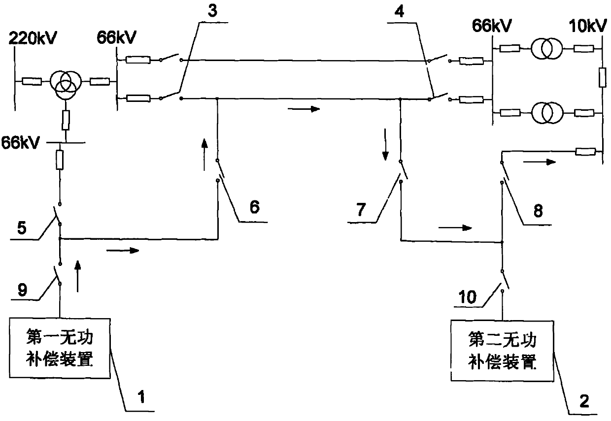
[0067] Specific implementation mode three: the following combination figure 2 and image 3 Describe this embodiment. The difference between this embodiment and Embodiment 1 is that the first reactive power compensation device 1 and the second reactive power compensation device 2 use capacitors, capacitor banks or static var compensators SVC, and others are the same as those of the embodiment. One is the same.

[0068] There is no need to add special ice-melting equipment, such as adjustable reactors, DC rectifier and voltage regulator devices, etc. Capacitors, capacitor banks or static var compensators SVC can be used for connection in the existing power grid, and the reactive current loop input at the end of the line can be formed. De-ice the lines. Save money, manpower and material resources.


PUM


Abstract

The invention discloses an ice-melting method of a transmission line with ends thereof infused with reactive current, belonging to the field of high-voltage transmission system, the purpose of the invention is to solve the problems that high-capacity adjustable inductance has no molding equipment when the ice-melting method of adjusting load of capacitance compensating inductance is adopted and that the equipment investment is large. In the invention, the ice-melting method is carried out on a transmission line between two substations; the method comprises the following steps: firstly disconnecting the transmission line on which ice melting needs to be carried out from a power grid, secondly disconnecting a reactive power compensation device which is used for improving power factor in thetwo substations from the power grid, thirdly connecting the reactive power compensation device of one substation onto a bus of the other substation through the transmission line on which ice melting needs to be carried out to form an ice-melting loop which is in a state of reactive overcompensation, and heating the transmission line to reach ice-melting effect. The ice-melting method of the invention is applied in high voltage line ice-melting.

Description

technical field [0001] The invention relates to a method for melting ice of a power transmission line by injecting reactive current at the end of the line, and belongs to the field of high-voltage power transmission systems. Background technique [0002] With global climate change, large-scale meteorological disasters occur frequently all over the world. Northern Europe and North America have repeatedly encountered large-scale ice and snow disasters. In recent years, major ice damage accidents have occurred frequently in my country. Following the large-scale ice damage accident across the country in 2005, in January 2008, most provinces and cities in southern my country encountered severe ice and snow weather that had not been encountered in many years. The icing accident on transmission lines caused large-scale blackouts and affected communications, transportation , tourism and other related industries have brought huge losses to the national economy. During the period of...

Claims


Application Information

Patent Timeline
Patent Type & Authority Patents(China)
IPC IPC(8): H02G7/16H02J3/18
CPCY02E40/30
Inventor 刘刚赵学增王久玲陈永辉姜世金梁岩刘子军王栋刘志平
Owner JIXI ELECTRIC POWER BUREAU
Why Eureka
Try Eureka