De-icing device with wattless current injected in the end of transmission line

A transmission line and ice melting technology, which is applied in the installation of cables, electrical components, overhead installation, etc., can solve the problems of large-capacity adjustable inductance without forming equipment and large equipment investment, and achieves favorable development and implementation, and good economic benefits. , good stability

Active Publication Date: 2011-04-27
JIXI ELECTRIC POWER BUREAU +1
View PDF0 Cites 0 Cited by
  • Summary
  • Abstract
  • Description
  • Claims
  • Application Information

AI Technical Summary

Problems solved by technology

[0008] The purpose of the present invention is to solve the problem of large-capacity adjustable inductance without forming equipment and large equipment investment in the method of using capacitance compensation and inductance to adjust the negative ice melting method, and provides a kind of ice-melting device that injects reactive current at the end of the transmission line

Method used


Image

  • De-icing device with wattless current injected in the end of transmission line
  • De-icing device with wattless current injected in the end of transmission line
  • De-icing device with wattless current injected in the end of transmission line

Examples


specific Embodiment approach 1

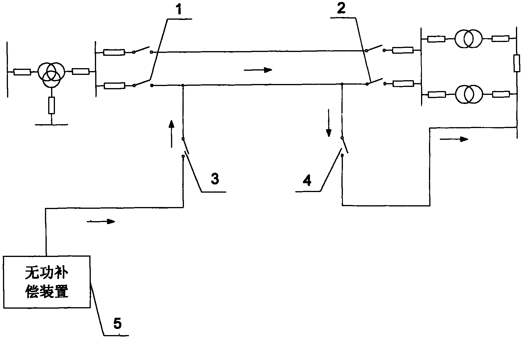
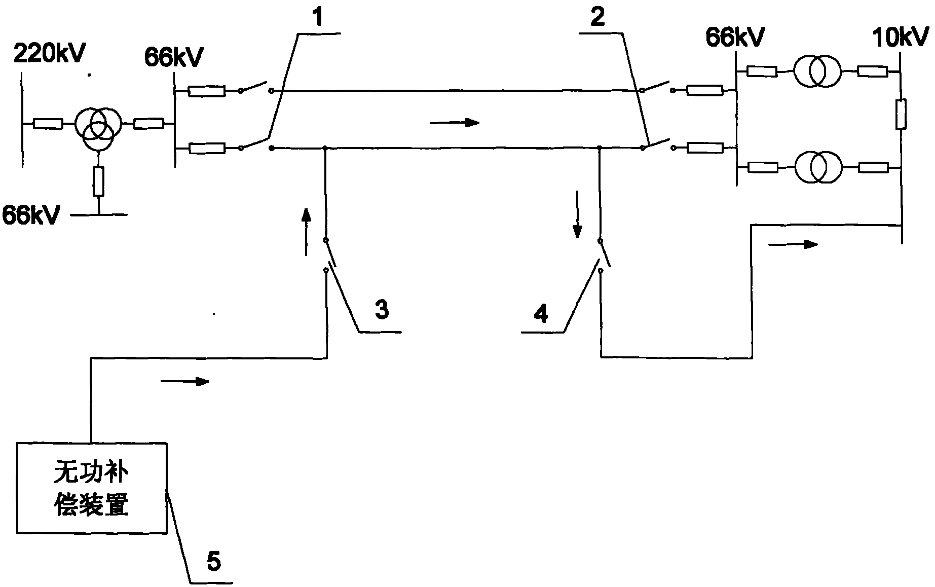
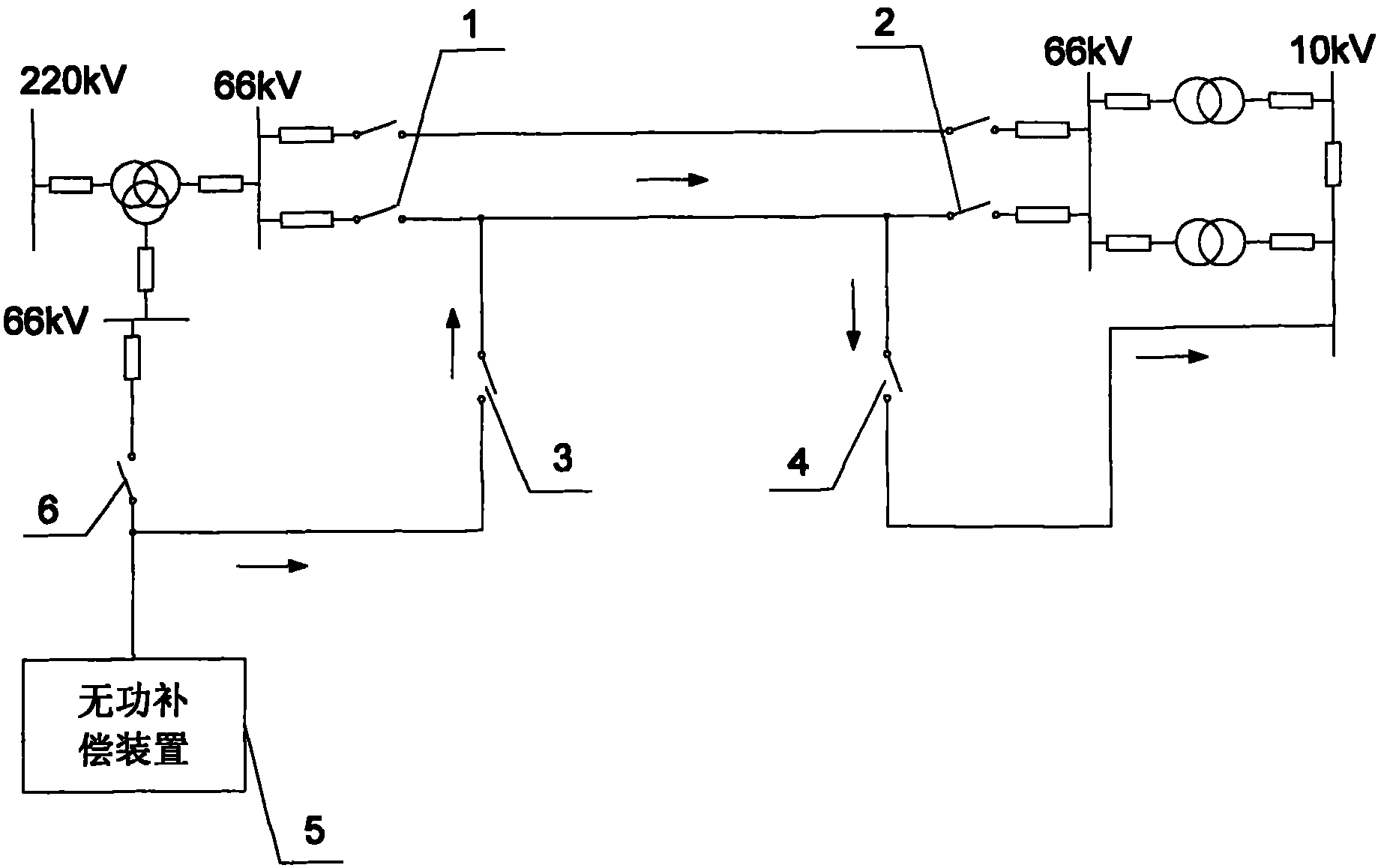
[0017] Specific implementation mode one: the following combination figure 1 Describe this embodiment, this embodiment includes a first isolating switch 1 and a second isolating switch 2, the two ends of the transmission line are respectively provided with the first isolating switch 1 and the second isolating switch 2, and it also includes a near-end deicing isolating switch 3 , the far-end ice-melting isolating switch 4 and the reactive power compensation device 5, the reactive power compensating device 5 is connected to one end of the near-end ice-melting isolating switch 3, and the connection point between the first isolating switch 1 and the near-end of the transmission line is connected to the ice-melting isolating switch The other end of 3 is connected, the connection point between the second isolating switch 2 and the far end of the transmission line is connected to one end of the remote deicing isolating switch 4, and the other end of the remote deicing isolating switch ...

specific Embodiment approach 2

[0018] Specific implementation mode two: the following combination Figure 2 to Figure 5 This embodiment is described. The difference between this embodiment and the first embodiment is that the reactive power compensation device 5 uses a capacitor, a capacitor bank or a static var compensator SVC, and other components and connections are the same as those of the first embodiment.

[0019] The transmission line refers to the transmission line between two substations. In this embodiment, the reactive power compensation device 5 adopts a capacitor, a capacitor bank or a static var compensator SVC connected in parallel on the busbar of the near-end substation, that is, the near-end substation The reactive power compensation device 5 originally used to improve the power factor is connected to the remote substation for melting ice of the transmission line. In this way, there is no need to add special ice melting equipment, such as adjustable reactors, DC rectifying and voltage regul...


PUM


Abstract

A de-icing device with wattless current injected in the end of a transmission line belongs to the field of high voltage power transmission systems. The invention aims at solving the problems of no forming equipment for a high-capacity adjustable inductor and large equipment investment by adopting a capacitance compensation inductance negative adjustment de-icing method. Two ends of the transmission line are respectively provided with a first isolating switch and a second isolating switch. The de-icing device also comprises a near-end de-icing isolating switch, a distant-end de-icing isolatingswitch and a reactive power compensator which is connected with one end of the near-end de-icing isolating switch. The connection point of the first isolating switch and the near end of the transmission line is connected with the other end of the de-icing isolating switch. The connection point of the second isolating switch and the distant end of the transmission line is connected with one end ofthe distant-end de-icing isolating switch, the other end of which is connected with a secondary bus of a distant-end transformer. The de-icing device is used for de-icing of high voltage lines.

Description

technical field [0001] The invention relates to an ice-melting device for injecting reactive current at the end of a power transmission line, belonging to the field of high-voltage power transmission systems. Background technique [0002] With global climate change, large-scale meteorological disasters occur frequently all over the world. Northern Europe and North America have repeatedly encountered large-scale ice and snow disasters. In recent years, major ice damage accidents have occurred frequently in my country. Following the large-scale ice damage accident across the country in 2005, in January 2008, most provinces and cities in southern my country encountered severe ice and snow weather that had not been encountered in many years. The icing accident on transmission lines caused large-scale blackouts and affected communications, transportation , tourism and other related industries have brought huge losses to the national economy. During the period of combating ice d...

Claims


Application Information

Patent Timeline
Patent Type & Authority Patents(China)
IPC IPC(8): H02G7/16
Inventor 刘刚赵学增王久玲陈永辉姜世金梁岩刘子军王栋刘志平
Owner JIXI ELECTRIC POWER BUREAU
Why Eureka
Try Eureka