Crankshaft rocker type speed reducer

A deceleration device and rocker arm type technology, which is applied to transmission devices, belts/chains/gears, mechanical equipment, etc., can solve the problems of difficult manufacturing, low transmission efficiency, and high production costs, and achieve easy implementation, improved transmission efficiency, low cost effect

Inactive Publication Date: 2010-01-06
杨智勇
View PDF0 Cites 3 Cited by
  • Summary
  • Abstract
  • Description
  • Claims
  • Application Information

AI Technical Summary

Problems solved by technology

Therefore, due to the above reasons, these traditional transmission methods have the disadvantages of high noise, large volume, large wear, difficult maintenance, difficult manufacturing, high production cost, and low transmission efficiency.

Method used


Image

  • Crankshaft rocker type speed reducer
  • Crankshaft rocker type speed reducer
  • Crankshaft rocker type speed reducer

Examples


Embodiment 1

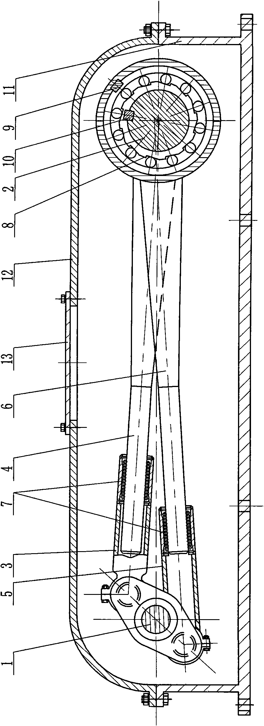
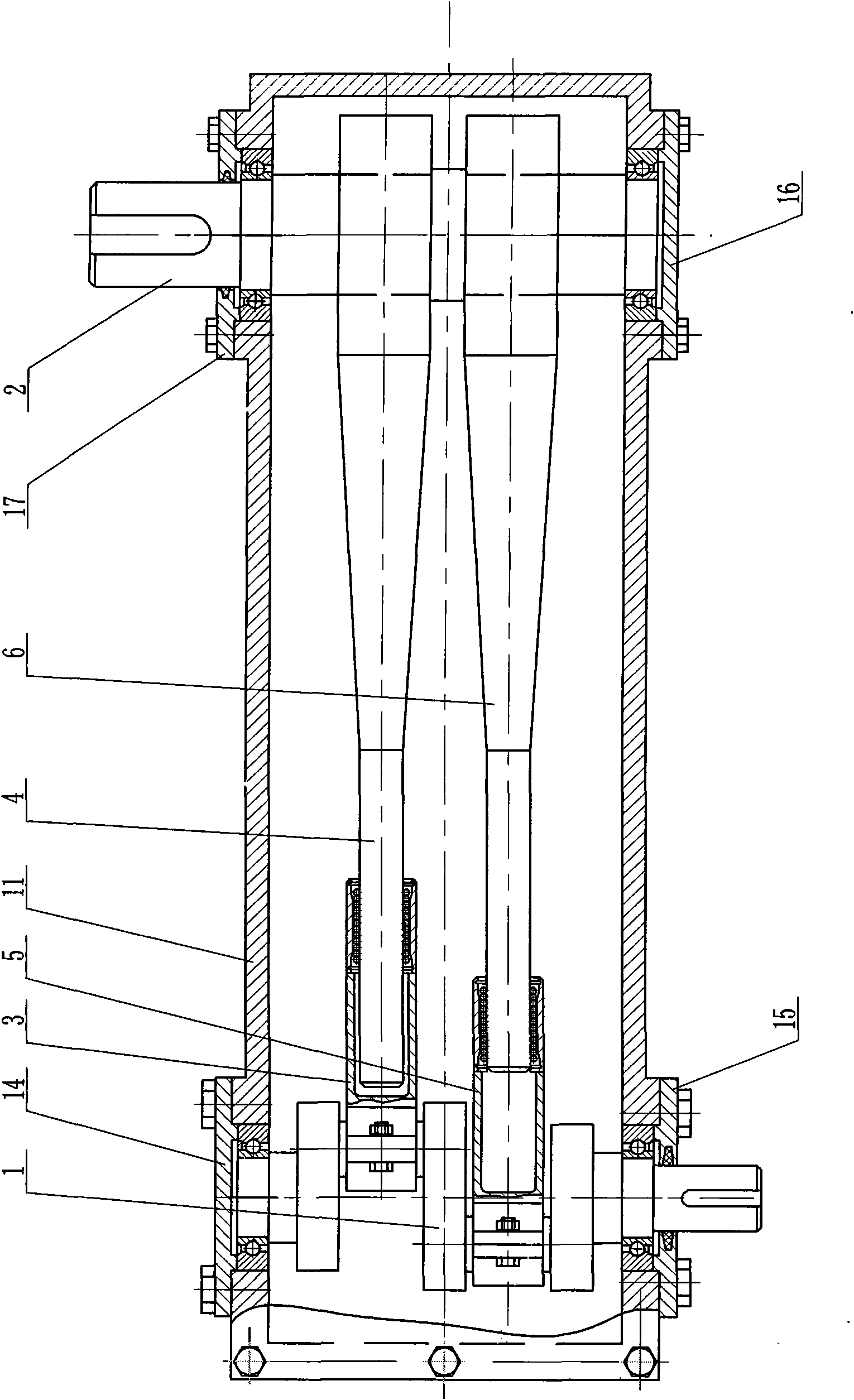
[0024] Such as figure 1 , figure 2 As shown, this embodiment consists of input shaft 1, output shaft 2, first link 3, first rocker arm 4, second link 5, second rocker arm 6, sliding bearing 7, ratchet wheel 8, first flat key 9. The second flat key 10, the box body seat 11, the box cover 12, the observation hole cover 13, the crankshaft blind cover 14, the crankshaft through cover 15, the output shaft blind cover 16, and the output shaft through cover 17 are composed of components. The box body base 11 and the box cover 12 are both box-shaped structures with one end open and the other closed. The open ends of the two are buckled together and fixed by bolts to form the box body of the deceleration device. An observation hole is opened in the center of the top of the box cover 12, the observation hole is sealed by the observation hole cover 13, and the observation hole cover 13 is fixed to the box cover 12 by bolts.

[0025] From figure 1 , figure 2 It can be seen that the input s...

Embodiment 2

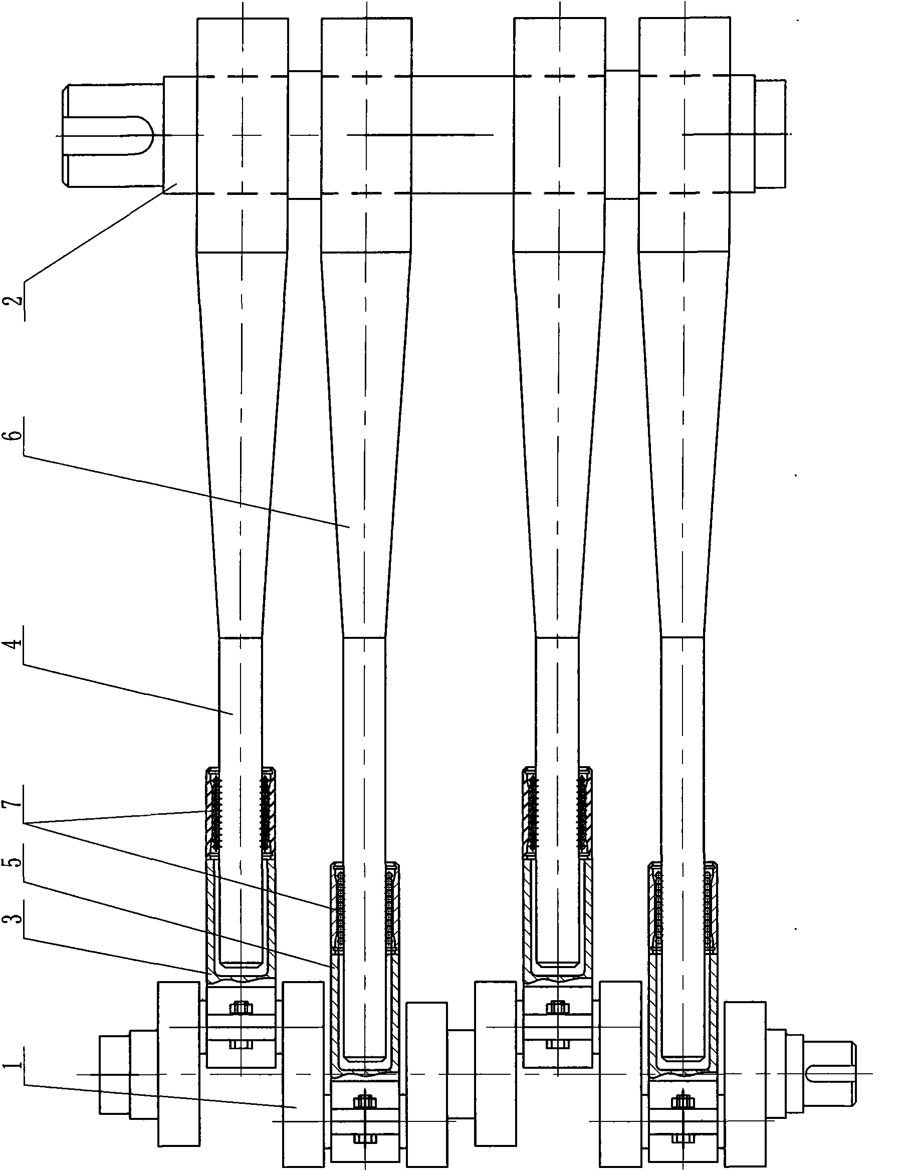
[0029] Such as image 3 As shown, there are two sets of crankshafts along the axial direction on the crankshaft, and each set of crankshafts is equipped with two sets of connecting rod, rocker arm and one-way device. The setting method of each group of cranks, and the connection relationship among the cranks, connecting rod, rocker arm and unidirectional device in each group are the same as those in the first embodiment, and will not be repeated here. In the same way, 3 groups or more than 3 groups of crankshafts can be arranged along the axial direction on the crankshaft, and a corresponding number of connecting rods, rocker arms and unidirectional devices can be equipped.


PUM


Abstract

The invention discloses a crankshaft rocker type speed reducer. An input shaft and an output shaft are supported on a box body through bearings; the input shaft is a crankshaft; one to three groups of bell cranks are arranged on the crankshaft along the axial direction; the number of each group of bell cranks is two; an alternate angle between the two bell cranks is 180 degrees in the same group; the first bell crank is connected with one end of a first rocker through a first connecting rod in the same group, and the other end of the first bell crank is sleeved on the output shaft through an isolator; the second bell crank is connected with one end of a second rocker through a second connecting rod in the same group, and the outer end of the second rocker is also sleeved on the output shaft through an isolator. The invention not only adopts a linear bearing movement mode with high precision at a high-speed end to effectively control the transmission noise, the abrasion, and the like of the crankshaft rocker type speed reducer, but also adopts the isolator capable of bearing the high pulling torque at a low-speed end to improve the transmission efficiency. Because the volume of the whole device is reduced by adopting the crankshaft, the connecting rods, the rocker, the isolators and other structural modes, the production cost is also reduced.

Description

Technical field [0001] The invention belongs to the technical field of mechanical transmission, and in particular, relates to a crankshaft rocker arm type deceleration device. Background technique [0002] At the present stage, the mechanical transmission methods used in the reduction device in production applications mainly include gear transmission, belt transmission, chain transmission and other forms. Gear transmission is power transmission through meshing gear sets. As the output power and output torque increase, the transmission ratio and gear modulus are also required to increase, or the transmission stages of the transmission mechanism must be increased, resulting in The volume of the gear transmission is also inevitably increased. With the increase of output power and output torque of belt drive and chain drive, the diameter of the pulley or the number of sprocket teeth and the center distance must be increased, or the number of transmission stages of the transmission m...

Claims


Application Information

Patent Timeline
Patent Type & Authority Applications(China)
IPC IPC(8): F16H21/18
Inventor 杨智勇
Owner 杨智勇
Why Eureka
Try Eureka