

Structure for lowering load of rotary compressor
A rotary compressor and load technology, which is applied in the direction of rotary piston machinery, rotary piston pumps, mechanical equipment, etc., can solve the problems of reduced service life, mechanical wear, increased compressor load, reduced compressor performance and reliability, etc. problem, achieve the effect of reducing power, reducing mechanical wear and load, and improving performance and reliability
Inactive Publication Date: 2003-07-02
LG ELECTRONICS (TIANJIN) APPLIANCES CO LTD
View PDF0 Cites 2 Cited by
- Summary
- Abstract
- Description
- Claims
- Application Information
AI Technical Summary
Problems solved by technology
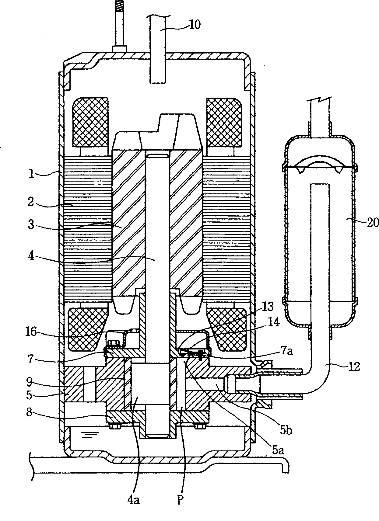
[0011] However, in the above-mentioned rotary compressor, when the refrigerant gas is compressed, the end of the rolling piston 9 is in contact with the main bearing 7 and the auxiliary bearing 8, so that mechanical wear and an increase in the load of the compressor inevitably occur, resulting in a loss of performance of the compressor. and reduced reliability, thereby reducing service life
Method used
View moreImage
Smart ImageViewing Examples

Examples
Embodiment 1
[0046] A contact surface of the rolling piston 51 and the main bearing 53 forms a groove 57a or 57c.
Embodiment 2
[0048] The contact surface of the rolling piston 51 and the auxiliary bearing 55 forms a groove 57b or 57d.
Embodiment 3
[0050] The contact surfaces of the rolling piston 51 with the main bearing 53 and the auxiliary bearing 55 form grooves 57a, 57b or 57c, 57d.
Login to View More PUM
 Abstract
A structure for decreasing load of vortex-type compressor is composed of rolling piston, primary bearing and secondary bearing, and features that a recess is made on at least surface of them to decrease the contact area, so reducing friction and load.
Description
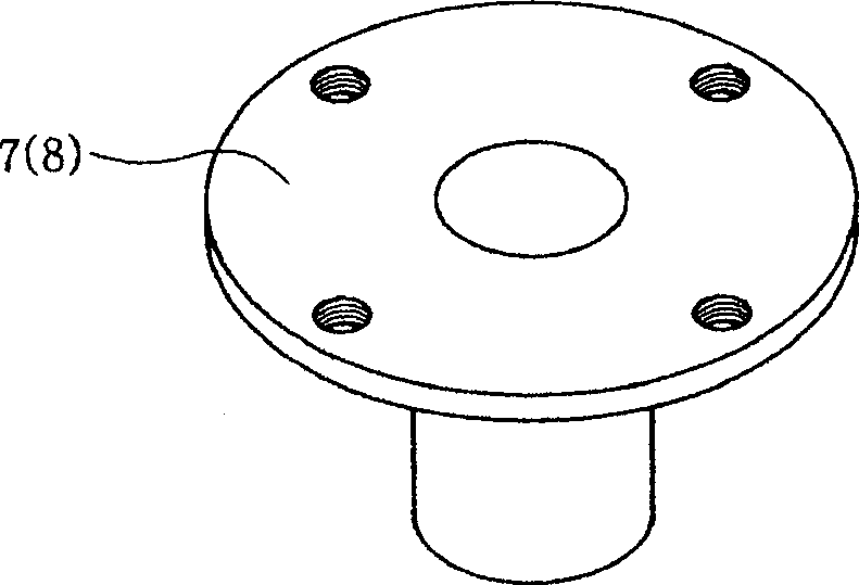
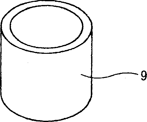
technical field [0001] The invention relates to a rotary compressor, in particular to a load-reducing structure of the rotary compressor. Background technique [0002] figure 1 is a sectional view of a conventional rotary compressor, figure 2 is an oblique view of a main or auxiliary bearing of conventional technology, image 3 An oblique view of a rolling piston of conventional technology. [0003] Refer to the above Figure 1 to Figure 3 It can be seen that a traditional compressor is composed of a casing 1, a motor provided inside the casing 1 to provide power, and a compression structure driven by the motor to compress refrigerant. The motor consists of a stator 2 and a rotor 3 fixed in a casing 1 . The compression structure is set in the casing 1, located at the lower part of the rotor 3, and consists of the rotating shaft 4, the eccentric shaft 4a below it, the gas compression chamber P, the cylinder 5, the main bearing 7, the auxiliary bearing 8 and the rolling ...
Claims
Login to View More Application Information
Patent Timeline
 Patent Type & AuthorityApplications(China)
IPC IPC(8): F04C18/02
Inventor郑仁修
OwnerLG ELECTRONICS (TIANJIN) APPLIANCES CO LTD