Driving tool

A work tool and work technology, applied in nailing tools, manufacturing tools, etc., can solve the problems of transmission, difficult to drive the wheel, etc., and achieve the effect of improving the striking force and improving the power transmission.

Inactive Publication Date: 2011-06-01
MAKITA CORP
View PDF1 Cites 0 Cited by
  • Summary
  • Abstract
  • Description
  • Claims
  • Application Information

AI Technical Summary

Problems solved by technology

[0003] However, in a structure in which the driving member is sandwiched between the fixed roller and the driving wheel and moved linearly, it is difficult to say that a sufficient force in the linear direction is transmitted from the driving wheel to the driving member (the driving member drives the driver into the driving member). The force of the workpiece, that is, the impact force), there is still room for improvement on this point

Method used


Image

  • Driving tool
  • Driving tool
  • Driving tool

Examples


no. 1 approach

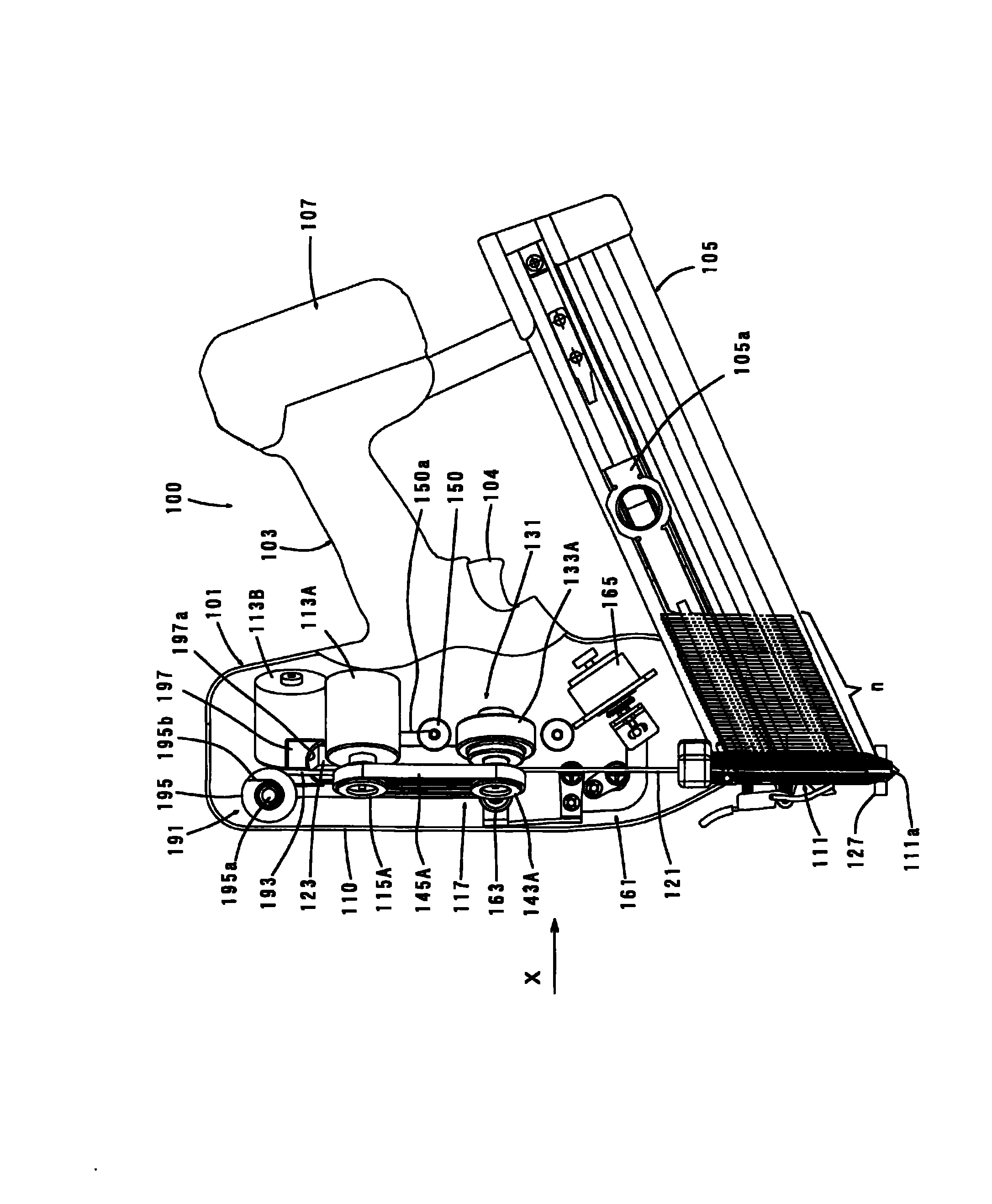
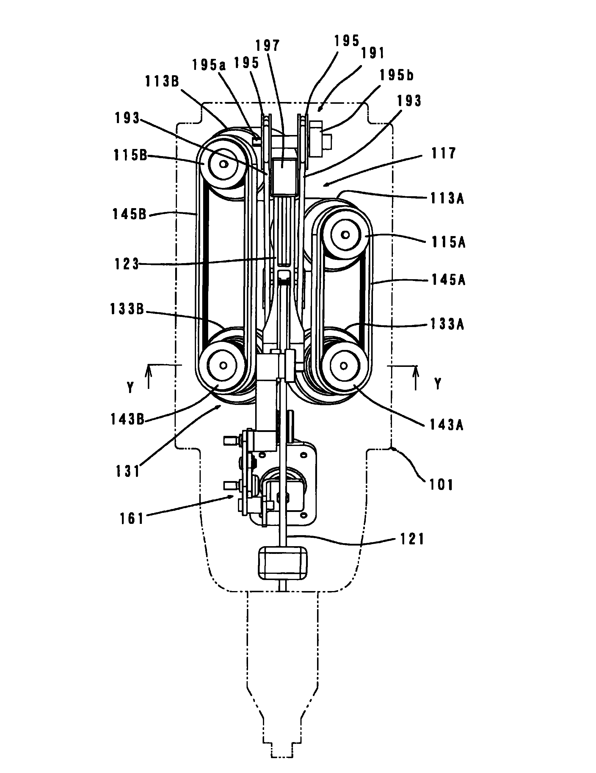
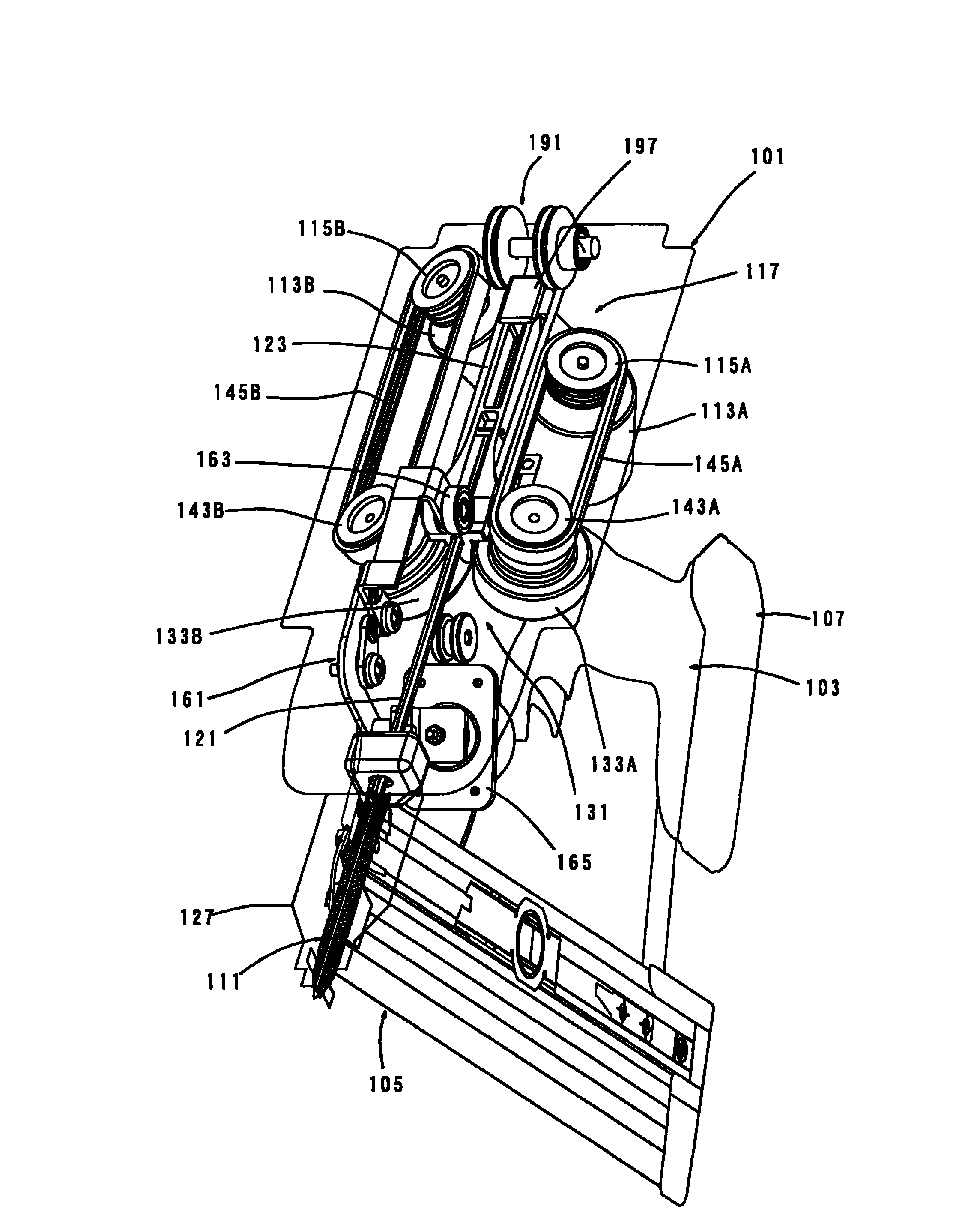
[0040] refer to Figure 1 to Figure 6 The first embodiment of the present invention will be described in detail. This embodiment will be described using a battery-operated nail driver as an example of a driving tool. exist figure 1 The whole of the nailing machine according to this embodiment is shown in . exist figure 2 China and Israel figure 1 The X-direction view shows the main parts of the nailing machine, in image 3 The main parts of the nailing machine are shown in perspective view. In addition, in Figure 4 shown in the figure 2 The cross-sectional structure of the Y-Y line. Furthermore, in Figure 5 Shows the pressing mechanism that presses the driver supporting platform on the flywheel, in Figure 6 The driver support table and driver are shown in .

[0041] Such as figure 1 As shown, the nailing machine 100, generally speaking, the main body structure includes: the main body 101 forming the shell of the nailing machine 100; the handle 103 held by the ...

no. 2 approach

[0119] Then refer to Figure 15 ~ Figure 17 A second embodiment of the present invention will be described. Figure 15 It is a side view showing the whole of the nailing machine, Figure 16 is a cross-sectional view illustrating a first arrangement example related to a V-shaped arrangement of a flywheel and a motor, Figure 17 is a cross-sectional view showing a second arrangement example related to the V-shaped arrangement of the flywheel and the motor.

[0120] In the second embodiment, a direct coupling method in which the pair of flywheels 133A, 133B are directly driven by the drive motors 113A, 113B without using a power transmission member is adopted. The rest of the configuration is substantially the same as that of the above-mentioned first embodiment. Therefore, descriptions of parts other than the direct coupling of the flywheel and the motor and the structures associated therewith will be omitted. In addition, the same symbols as those used in the description of...


PUM


Abstract

A driving tool for driving a driving member into a member to be worked transmits power to movable bodies in an improved manner. The driving tool has rotatingly driven first and second rotating bodies (133A, 133B), the movable bodies (121, 123) movable in the direction in which the driving member is struck, V-shaped first and second contact surfaces (124a) formed on the movable bodies (121, 123), and a pressing member (163) for applying force to the movable bodies (121, 123) so that they are pressed against the first and second contact bodies (124a) and against first and second rotating bodies(133A, 133B). The driving tool further has a first motor (113A) for driving the first rotating body (133A) and a second motor (113B) for driving the second rotating body (133B).

Description

technical field [0001] The present invention relates to a driving tool for driving a driving part such as a nail into a workpiece. Background technique [0002] As a driving mechanism for driving a driving element as a movable body, for example, Japanese Patent Application Laid-Open No. 2006-142392 (Patent Document 1) discloses a driving tool in the form of a driving wheel (rotating body). In the above-mentioned gazette, there is described a nailing structure in which a driving member as a movable body for driving (beating) a nail is sandwiched between a driving wheel rotationally driven by an electric motor and a fixed roller to move the driving member linearly. machine. [0003] However, in a structure in which the driving member is sandwiched between the fixed roller and the driving wheel and moved linearly, it is difficult to say that a sufficient force in the linear direction is transmitted from the driving wheel to the driving member (the driving member drives the dri...

Claims


Application Information

Patent Timeline
Patent Type & Authority Patents(China)
IPC IPC(8): B25C1/06
CPCB25C1/06
Inventor 平林伸治
Owner MAKITA CORP
Why Eureka
Try Eureka