
Cutting device

A desktop cutting machine, cutting machine technology, applied in the direction of sawing equipment, metal sawing equipment, sawing machine equipment, etc., can solve the problems of cumbersome locking and unlocking operations of sliding locking mechanisms, etc., to improve operability and improve operability Effect

Inactive Publication Date: 2013-06-26
MAKITA CORP
View PDF0 Cites 0 Cited by
  • Summary
  • Abstract
  • Description
  • Claims
  • Application Information

AI Technical Summary

Problems solved by technology

[0004] But there is still room for further improvement in the above-mentioned sliding locking mechanism in this prior art
For example, as far as the locking mechanism of the prior art is concerned, because it either utilizes the axial movement generated by the rotation of the screw rod (stop bolt) to directly push the slide bar, or uses a block-shaped stop member Push the slide bar to lock the action of the slide mechanism. Therefore, the user needs to hold the screw rod and other rotary operating parts used for sliding lock with his hands, and perform several rotation operations on it. From a point of view, the locking and unlocking operations of the slide lock mechanism are cumbersome.

Method used


Image

  • Cutting device
  • Cutting device
  • Cutting device

Examples


Embodiment Construction

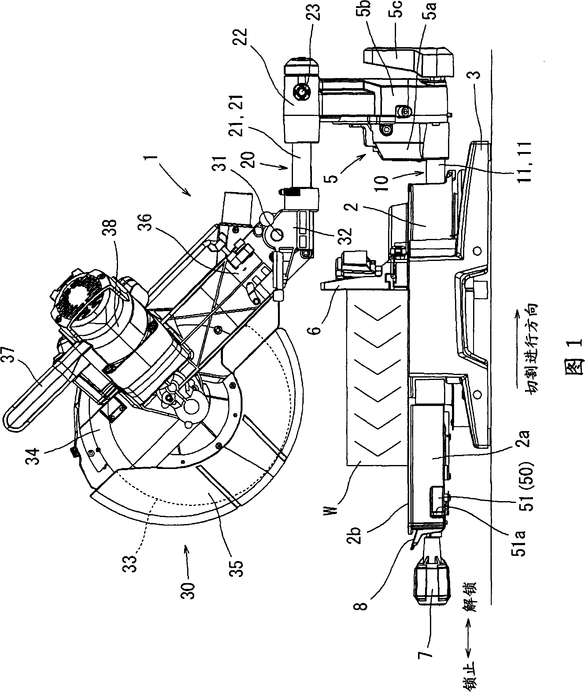
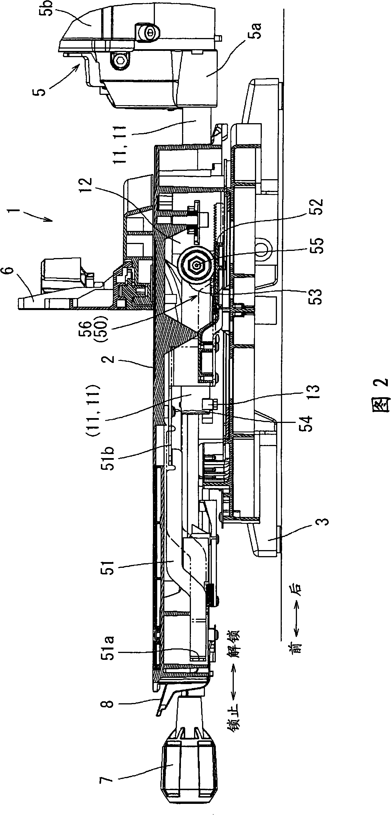
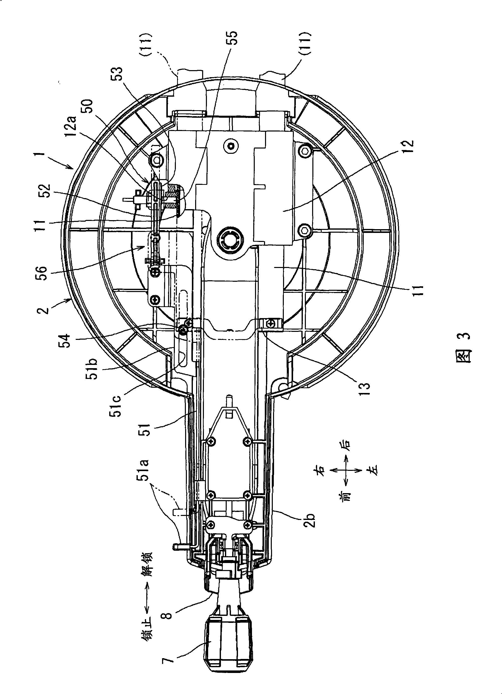
[0033] Next, specific embodiments of the present invention will be described with reference to FIGS. 1 to 8 . FIG. 1 shows the whole of a desktop cutting machine 1 in this embodiment. As shown in FIG. 1 , the user performs various operations on the desktop cutting machine 1 on the left side of the desktop cutting machine 1 . After the user moves the cutter body 30 downward, the user moves the cutter body 30 from the left side (closer side) to the right side in FIG. 1 to cut the workpiece W to be cut. Hereinafter, the direction in which dicing is performed is simply referred to as the direction in which dicing is performed. However, the front-back direction of components etc. is based on the user. Therefore, let the left side (the user's side) in FIG. 1 be the front side (close body side), and the right side in FIG. 1 be the rear side. In addition, the left-right direction of components etc. is based on the direction seen by a user.

[0034] The desktop cutting machine 1 ha...


PUM


Abstract

The present invention includes a cutting device (1) including a table (2) and a cutting unit (30) disposed on an upper side of the table (2) and vertically movably supported by the table (2) via a slide mechanism (10). The slide mechanism (10) enables the cutting unit (30) to slide in a sliding direction relative to the table (2) within a plane substantially parallel to a surface of the table (2). A slide lock mechanism (50; 60) can lock and unlock the sliding movement of the cutting unit (30) and includes an operation member (51a; 61a) operable to slide for locking and unlocking the sliding movement.

Description

technical field [0001] The present invention relates to a table cutting machine known as such as a sliding miter saw. Background technique [0002] This desktop cutting machine has: a table for supporting a piece to be cut, and a cutting machine body supported by the table and operable to move up and down relative to the table. The cutting machine body has a circular saw blade that is powered by an electric motor. Cutting can be performed by moving the cutting machine body downwards and cutting the rotating saw blade into the piece to be cut. Regarding the cutting machine body, it is not only possible to provide a cutting machine body that can not only be moved up and down but also slide along the plane direction of the table. When there is a sliding mechanism, the cutting machine body can be moved down first to allow the saw blade to cut into the piece to be cut, and then maintain this state so that the cutting machine body slides along the plane of the worktable to cut l...

Claims


Application Information

Patent Timeline
Patent Type & Authority Patents(China)
IPC IPC(8): B23D45/04
CPCB23D45/048B27B5/29Y10T83/7697Y10T83/7693Y10T83/7772Y10T83/8736Y10T83/7788
Inventor 可儿利之山村刚
Owner MAKITA CORP
Learn More