
Scanning device and scanning method

A technology of scanning device and scanning method, which is applied in the direction of image communication, electrical components, etc., can solve the problems of image brightness change, color cast, etc., and achieve the effect of convenient use

Inactive Publication Date: 2010-01-20
QISDA SUZHOU
View PDF0 Cites 10 Cited by
  • Summary
  • Abstract
  • Description
  • Claims
  • Application Information

AI Technical Summary

Problems solved by technology

This method is usually used on flat-bed scanners, but on portable scanners or sheet-fed scanners, due to design limitations, standard manuscripts fixed in the scanning device are generally not provided, and It is to provide an extra piece of standard manuscript to the user, and the user decides when to correct it, that is, this type of scanning device cannot be corrected at any time like a flatbed scanner
[0004] This creates a problem. When the scanner works for a period of time, or the ambient temperature of the scanner changes, the brightness of the LED in the CIS changes due to the ambient temperature change, resulting in changes in the brightness of the scanned image, and even color cast problems.

Method used


Image

  • Scanning device and scanning method
  • Scanning device and scanning method
  • Scanning device and scanning method

Examples


Embodiment Construction

[0026] In order to have a further understanding of the purpose, structure, features, and functions of the present invention, the following detailed descriptions are provided in conjunction with the embodiments.

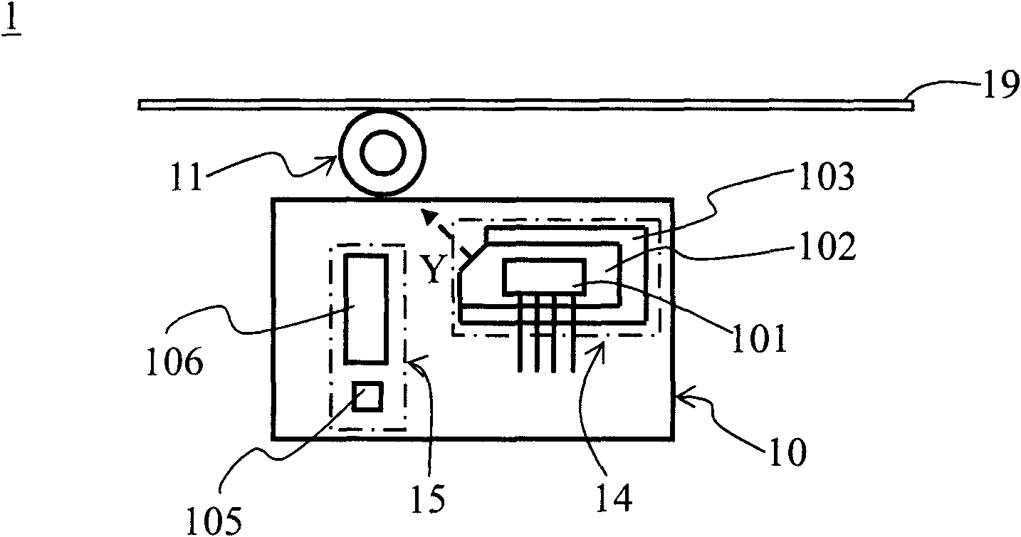
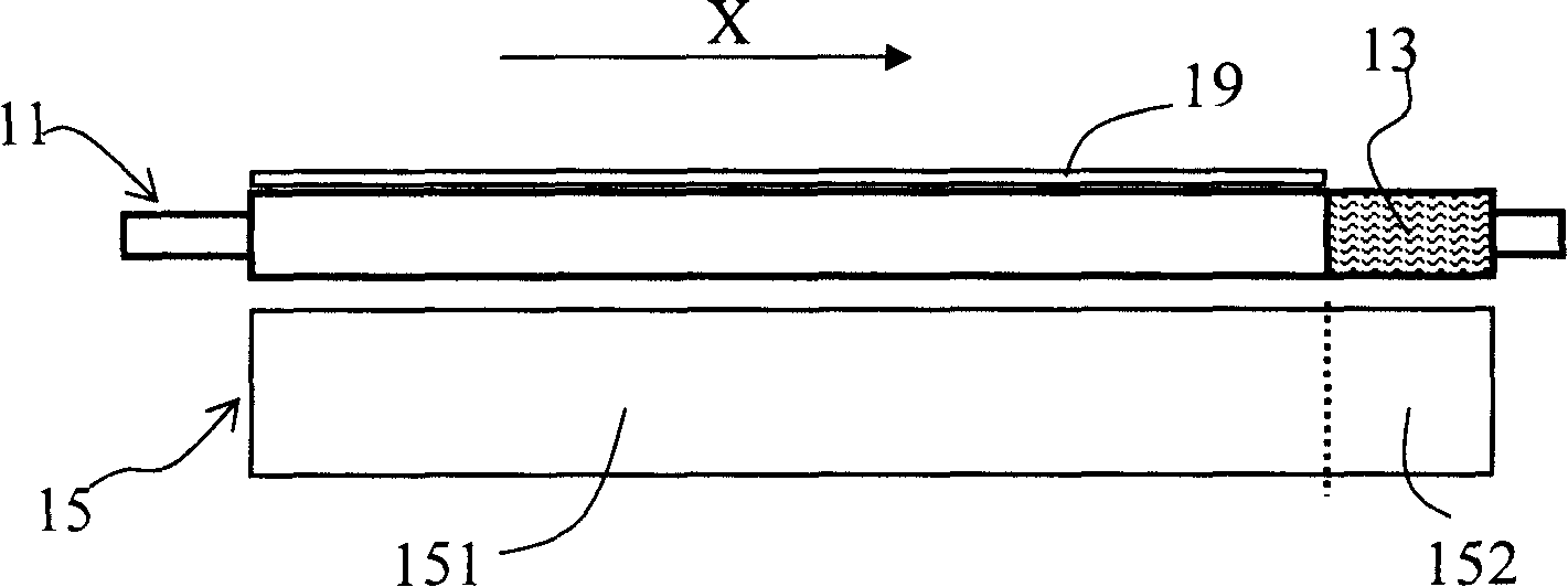
[0027] See figure 1 and figure 2 , figure 1 It is a schematic structural diagram of a scanning device 1 according to an embodiment of the present invention, figure 2 It is a schematic diagram of the position of the calibration unit 13 according to an embodiment of the present invention. The scanning device 1 includes a scanning module 10 , a paper feeding roller 11 and a calibration unit 13 . The scanning module 10 includes a line light source generating module 14 and a scanning module 15. The line light source generating module 14 includes a point light source 101, a light guide plate 102, and a housing 103. The light emitted by the point light source 101 along the first direction X is converted into a line through the light guide plate 102. The light source, t...


PUM


Abstract

The invention provides a scanning device and a scanning method. The scanning device comprises a scanning module, a paper feeding roller and a correction part. The scanning module comprises a light source generation module and a scanning module, wherein the light source generation module comprises a point light source, a light guide plate and a shell; light of the light source emitted along the first direction is converted into a line light source by the light guide plate; the light guide plate is arranged in the shell; the line light source emits light from an opening of the shell along the second direction; the scanning module comprises a scanning manuscript area and a correction area along the first direction, and light reflected by manuscript to be scanned is received in a manuscript scanning area. The paper feeding roller is arranged adjacent to the scanning module. A correction part is arranged on the shell or the paper feeding roller and corresponds to the correction area of a scanning module, and light reflected by the correction part is received in the correction area. The scanning device and the scanning method can solve the problems of color cast or brightness change caused by the temperature and the like, can be automatically corrected in real time and is more convenient to use.

Description

technical field [0001] The present invention relates to a scanning device and a scanning method, in particular to a scanning device and a scanning method with functions of automatically correcting brightness and color. Background technique [0002] Portable scanner products generally use CIS (contact image sensor) as the image acquisition device, and color CIS generally use RGB (red, green and blue) three-color LED (light-emitting diode) as the lighting source. Inside the portable scanner, because there are electronic components such as motors, drive circuit boards, and LED light sources that emit heat when they are working, and are affected by the temperature of the working environment, the temperature inside the scanning device will change, and this change will cause The change of LED brightness in CIS is then reflected in the brightness change on the scanned image. In addition, because the RGB three-color LEDs do not change completely with temperature, the RGB color of t...

Claims


Application Information

Patent Timeline
Patent Type & Authority Applications(China)
IPC IPC(8): H04N1/04H04N1/031
CPCH04N1/02835H04N1/1215H04N2201/03125H04N1/00013H04N1/00087H04N1/0005H04N1/00063H04N2201/03112H04N1/00034H04N1/193H04N2201/0081H04N2201/03141H04N1/125H04N2201/0096H04N1/00055H04N2201/03145H04N1/00023H04N1/00045H04N1/00002
Inventor 易永祥
Owner QISDA SUZHOU
Learn More