Supercharge Your Innovation With Domain-Expert AI Agents!

Brush manufacturing machine for circular brush

A technology for making machines and circular brushes, applied in the direction of brushes, applications, brush bodies, etc., can solve the problem of expensive devices, and achieve the effects of shortening manufacturing time, simple and rapid processing, and avoiding time loss.

Active Publication Date: 2013-01-16
ZAHORANSKY AG
View PDF1 Cites 0 Cited by
  • Summary
  • Abstract
  • Description
  • Claims
  • Application Information

AI Technical Summary

Problems solved by technology

However, such devices are relatively expensive, both in manufacture and in matching the different brush types

Method used


Image

  • Brush manufacturing machine for circular brush
  • Brush manufacturing machine for circular brush
  • Brush manufacturing machine for circular brush

Examples


Embodiment Construction

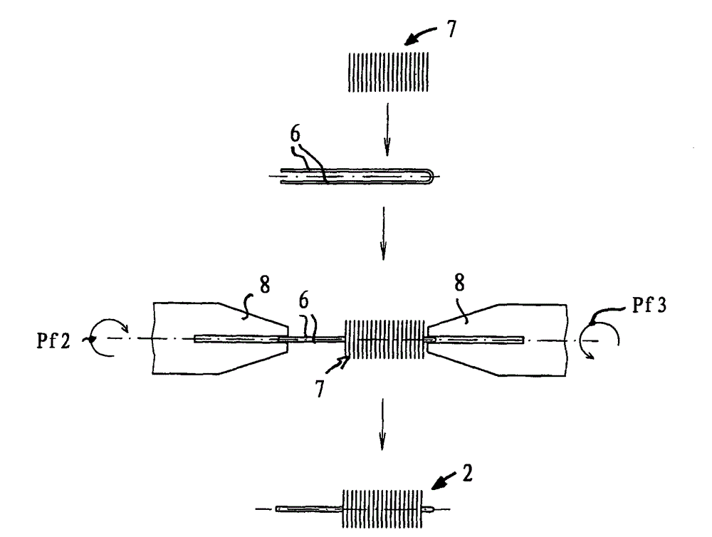
[0027] exist figure 1 The brush manufacturing machine 1 for round brushes 2 shown in a very simplified manner has two wire twisting devices 3a, 3b, which are mounted rotatably (arrow PF1) on Between an insertion position 4 and a processing position 5 .

[0028] On the insertion position 4, the metal wire 6 and the bristle wire 7 ( figure 2 ) into the wire twisting device 3a located there ( figure 1 ). The two wire twisting devices 3a, 3b each have two grippers 8 spaced apart from each other, by means of which the wires are clamped. The grippers 8 are respectively driven by a servomotor not shown, wherein the two grippers 8 of the wire twisting devices 3a, 3b are positioned according to the arrows Pf2 and Pf3 figure 2 in the opposite rotational motion.

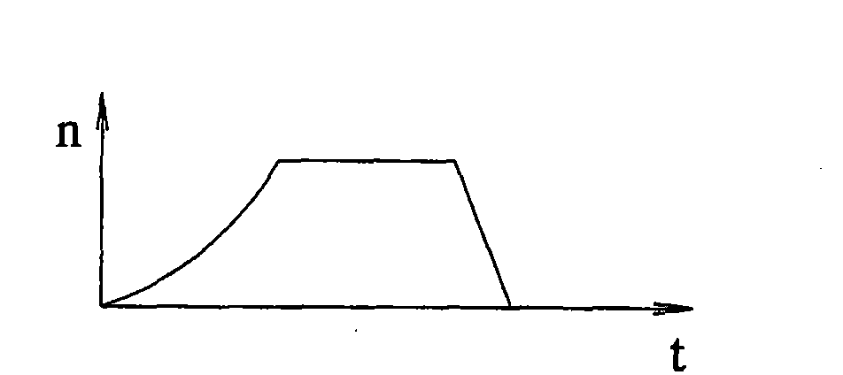
[0029] The servomotor is initially operated at a low rotational speed in order to prevent individual bristle filaments 7 from falling out. As soon as the bristle filaments 7 are securely clamped between the wires 6 , th...


PUM


Abstract

The machine (1) has two wire twisting devices (3a, 3b) positioned between an inserting place (4) and a processing and / or ejection place (5). The wire twisting devices are driven during the positioning movement between the inserting place and the processing and / or ejection place for twisting. The wire twisting devices are arranged at a rotatably supported drum and exhibit two gripping arms (8) for holding wires (6), where the arms are arranged at a distance from each other. A cooling device is provided for the wire twisting devices.

Description

technical field [0001] The invention relates to a brush maker for round brushes with bristles screwed in between wires, said brush maker comprising a bristle feeding device and a wire twisting device. Background technique [0002] In the manufacture of round brushes such as bottle brushes, toothbrushes or mascara brushes, the bristle filaments are positioned between two wires or between the two wire arms of a U-shaped bent wire and clamped to them by rotating the wire connected. In order to avoid slipping of the bristle filaments during rotation, the screw-in speed and thus the maximum possible processing speed are limited. [0003] From EP 1 917 886 A1 a method and a device for producing round brushes are known, in which the processing takes place on a plurality of downstream workstations. In particular, the bristle filaments are first screwed in at a reduced rotational speed in order to fix the bristle filaments between the wires. Next, the round brush is transferred to...

Claims


Application Information

Patent Timeline
Patent Type & Authority Patents(China)
IPC IPC(8): A46D3/05
CPCA46D9/02A46D3/05
Inventor P・施泰内布伦纳
Owner ZAHORANSKY AG
Features
  • R&D
  • Intellectual Property
  • Life Sciences
  • Materials
  • Tech Scout
  • Unparalleled Data Quality
  • Higher Quality Content
  • 60% Fewer Hallucinations
Learn More