Charging device

A technology of charging device and charging part, which is applied in the direction of circuit device, battery circuit device, secondary battery charging/discharging, etc., and can solve problems such as inability to charge, poor contact, etc.

Inactive Publication Date: 2010-02-03
HONG FU JIN PRECISION IND (SHENZHEN) CO LTD +1
View PDF4 Cites 9 Cited by
  • Summary
  • Abstract
  • Description
  • Claims
  • Application Information

AI Technical Summary

Problems solved by technology

[0004] However, if the angle of the robot's adjustment angle is not appropriate, the contact pins on it will not be able to make contact with the fixed electrical contacts on the wall or the contact will be poor, thus making it impossible to charge

Method used


Image

  • Charging device
  • Charging device
  • Charging device

Examples


Embodiment Construction

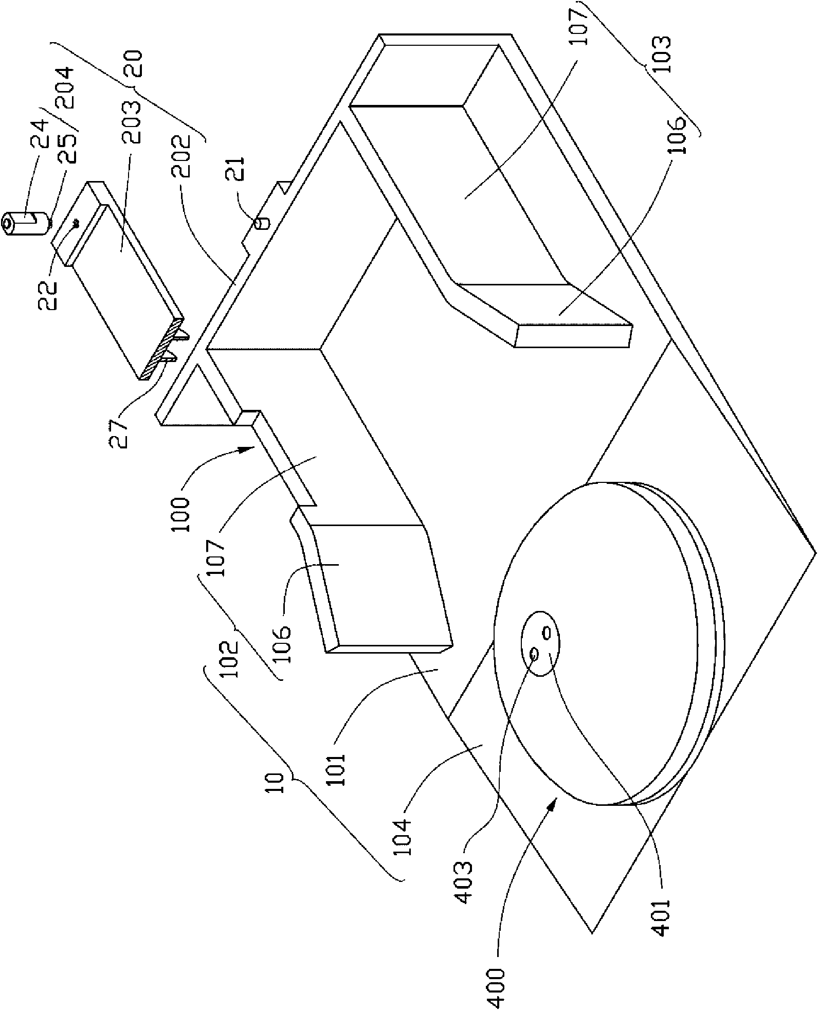
[0011] Such as figure 1 Shown is an exploded view of a preferred embodiment of the charging device and the mobile robot. The charging device 100 is used to charge the mobile robot 400. The charging device 100 includes a supporting part 10 and a charging part 20. The carrying part 10 is arranged on one side of the charging part 20 to facilitate guiding the robot 400 to move to the charging part 20 for charging. The charging unit 20 is used to charge the robot.

[0012] The mobile robot 400 has a substantially flat circular cone shape. The mobile robot 400 is provided with a rechargeable battery (not shown). Rechargeable batteries are used to provide power for mobile robots. The mobile robot 400 further includes a groove 401 arranged at the center of the top and two electrical contacts 403 arranged in the groove 401. The two electrical contacts 403 are electrically connected with the rechargeable battery.

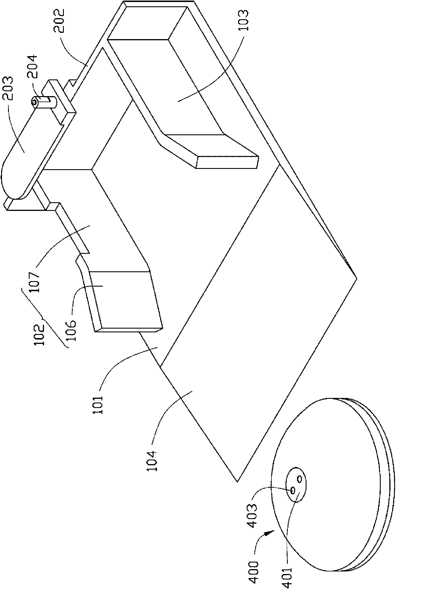
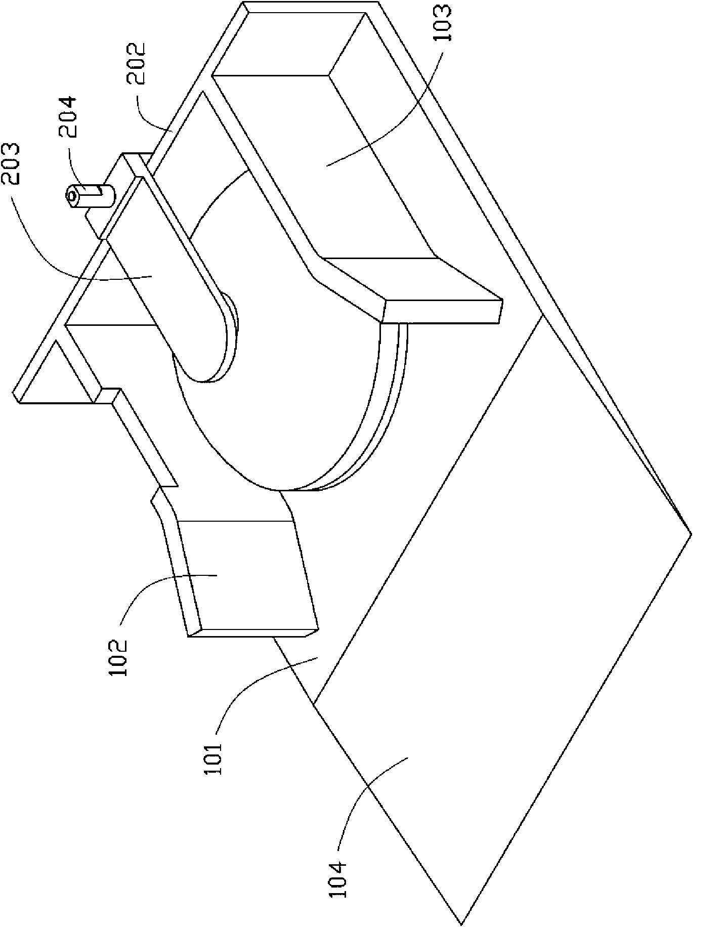
[0013] Such as figure 2 Shown as figure 1 A perspective view of the mi...


PUM


Abstract

A charging device is used for charging for a mobile robot and comprises a bearing part and a charging part which also comprises a supporting part, a rotating part and a driver, wherein, the bearing part is used for bearing the mobile robot; the charging part is used for charging for the mobile robot; the supporting part is arranged on the bearing part; the rotating part is fixedly connected on thesupporting part in a rotating manner; the driver is used for driving the rotating part to rotate; the rotating part is provided with a conducting plate and rotates by the driving of the driver, and leads the conducting plate to be electrically contacted with the electrical contact of the robot on the bearing part; the rotating part is driven by the driver to rotate to lead the conducting plate tobe separated from the robot after charging for the mobile robot is completed.

Description

Technical field [0001] The invention relates to a charging device, in particular to a mobile robot charging device. Background technique [0002] Mobile robots are usually used to complete a given task within a certain range. The mobile robot includes a rechargeable battery arranged inside and two electrical contacts arranged on the top and connected with the rechargeable battery. The rechargeable battery is used to provide power for the mobile robot. When the stored power of the rechargeable battery is lower than a predetermined reference value, the mobile robot will move to the charging device for charging according to the position signal sent by the charging device. [0003] The existing robot charging device includes a charging mechanism and a guiding mechanism. The charging mechanism is used for charging the robot, which is a fixed electrical contact set on the wall. The guiding mechanism has an inclined slope. When the rechargeable battery needs to be charged, the robot m...

Claims


Application Information

Patent Timeline
Patent Type & Authority Applications(China)
IPC IPC(8): H01M10/44
CPCY02E60/12H02J7/0044H01M10/44Y02E60/10
Inventor 黎雄褚永鸿
Owner HONG FU JIN PRECISION IND (SHENZHEN) CO LTD
Why Eureka
Try Eureka