
Valve cartridge with low point of contact for installation

A technology of spool and shell, applied to multi-way valves, valve devices, valve details, etc., can solve the problems of less freedom and increased cost

Active Publication Date: 2010-02-10
富俊水创新有限责任公司
View PDF1 Cites 1 Cited by
  • Summary
  • Abstract
  • Description
  • Claims
  • Application Information

AI Technical Summary

Problems solved by technology

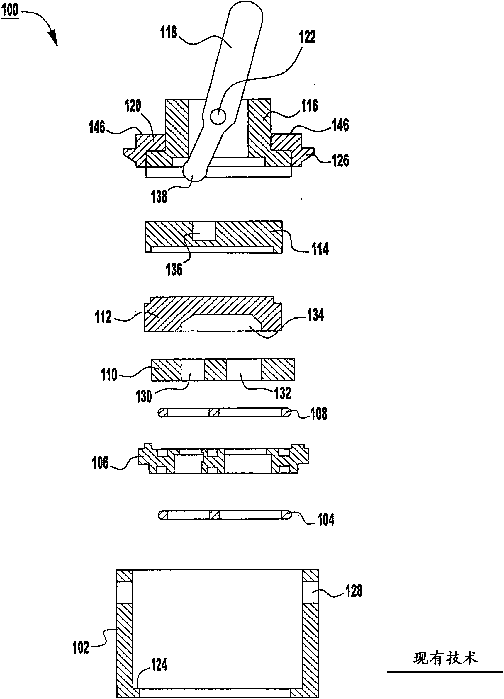
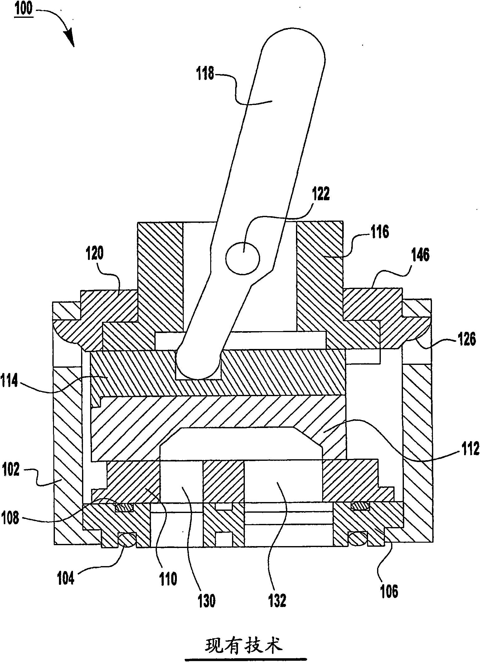
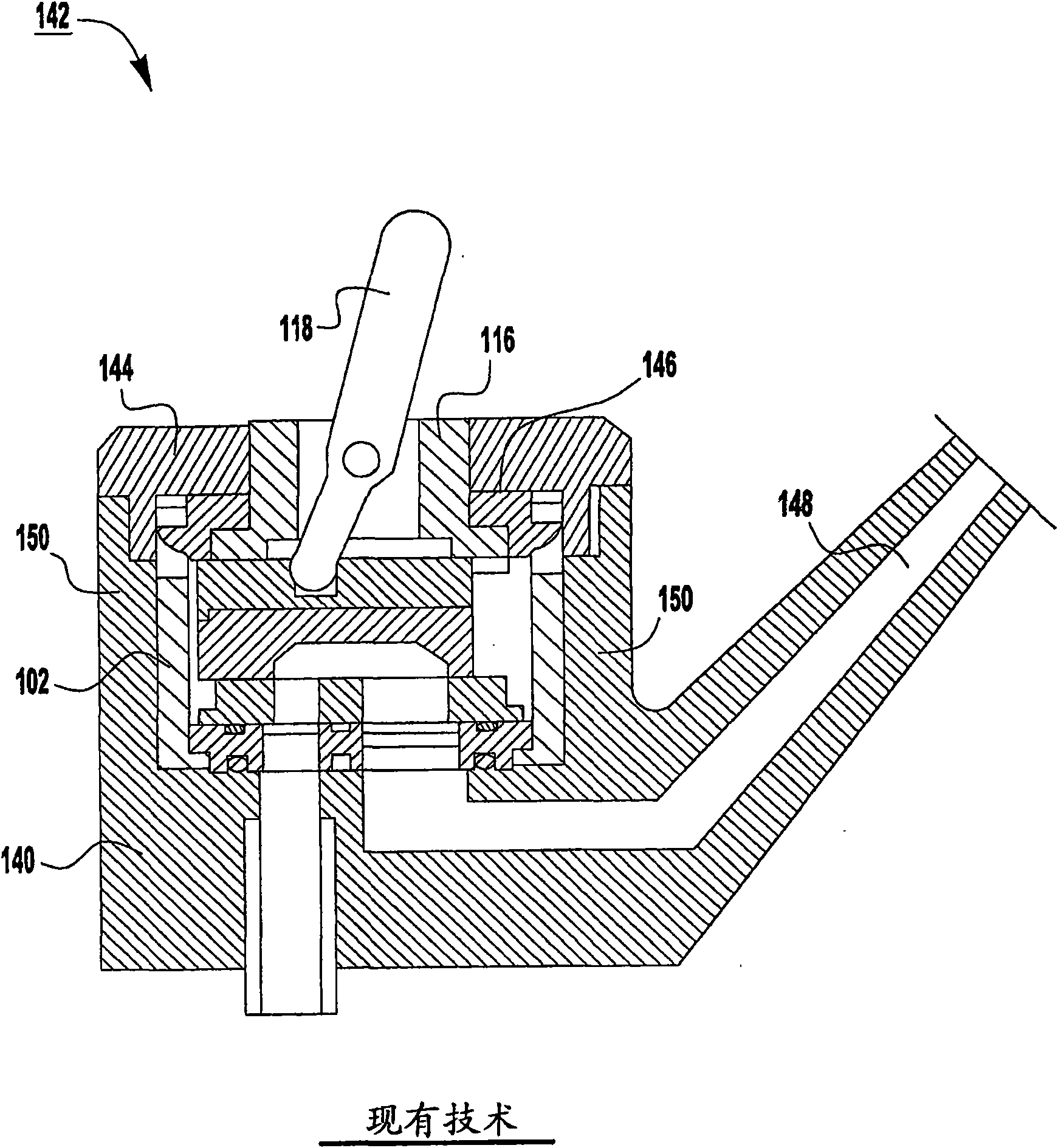
[0018] However, taller mounting lugs 146 have several disadvantages
For example, the taller mounting lug 146 results in less freedom in the design of the plumbing fixture for receiving the spool 200
In addition, taller mounting lugs 146 result in increased cost because the height of the sidewall 150 of the valve body 140 is typically at least as high as the height of the mounting lugs 140

Method used


Image

  • Valve cartridge with low point of contact for installation
  • Valve cartridge with low point of contact for installation
  • Valve cartridge with low point of contact for installation

Examples


Embodiment Construction

[0056] While the general concepts of the invention are susceptible of embodiments in many different forms, specific embodiments thereof are shown in the drawings and will be described in detail herein, it being understood that this disclosure is to be considered in accordance with the principles of the general concepts of the invention. for example. Therefore, the general concepts of the invention are not to be limited by the specific embodiments described herein.

[0057] The single handle spool 200 according to the exemplary embodiment has a low contact point for securing the spool 200 in the valve body 240 . Therefore, the spool 200 can overcome the disadvantages of the conventional valve box with high contact points.

[0058] Such as figure 2 with 10A As shown in FIG. 10C , the exemplary cartridge 200 has several separate components including a housing 202 , a bulb 204 , a pin 206 , a spring 208 , a bushing 210 , a flow plate 212 , a manifold 214 , and a base seal 216 ...


PUM


Abstract

A one-handle valve cartridge has a low point of contact for installing the valve cartridge in a valve body. A retention nut bears down on the low point of contact to secure the valve cartridge in thevalve body.

Description

[0001] related application [0001] This application is filed as a non-provisional patent application claiming priority and any other benefit to U.S. Provisional Patent Application No. 60 / 898,542, filed January 31, 2007, under 35 U.S.C. § 119(e), the entirety of which is adopted by References are included here. technical field [0002] The present invention relates generally to spools and, more particularly, to spools having low contact points for mounting the spool in a valve body. Background technique [0003] Typically, for a plumbing fixture (eg, faucet, tub spout, shower head), the valve body conveys water flowing from a main water source to a desired destination (eg, sink, tub, washbasin). The valve body usually has two water inlet passages through which cold water and hot water from the main water source can flow respectively. The valve body also has a water outlet passage through which cold water, hot water, or a mixture of cold and hot water can be discharged to ...

Claims


Application Information

Patent Timeline
IPC IPC(8): F16K27/04
CPCF16K27/045F16K31/605F16K11/0787Y10T137/6007Y10T137/6011Y10T137/86493Y10T137/86815
Inventor M·S·凯西克W·R·塔克
Owner 富俊水创新有限责任公司
Learn More