A pad retention device

A technology for retaining devices, pads, applied in the direction of axial brakes, brake types, brake components, etc.

Inactive Publication Date: 2008-11-12
BENTLEY MOTORS
View PDF0 Cites 2 Cited by
  • Summary
  • Abstract
  • Description
  • Claims
  • Application Information

AI Technical Summary

Problems solved by technology

[0003] A disadvantage of calipers with cylindrical abutment pins is that there are two forms of noise, pad knock and pad rattle, which are related to the way the pads are seated in the caliper

Method used


Image

  • A pad retention device
  • A pad retention device
  • A pad retention device

Examples


Embodiment Construction

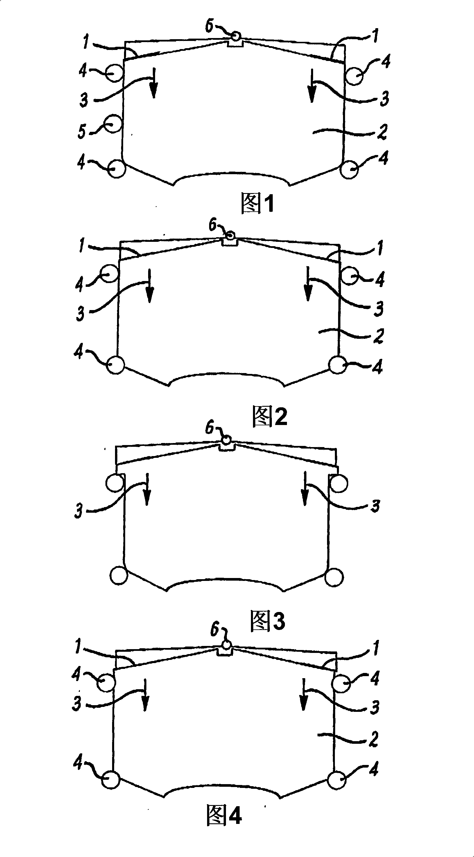
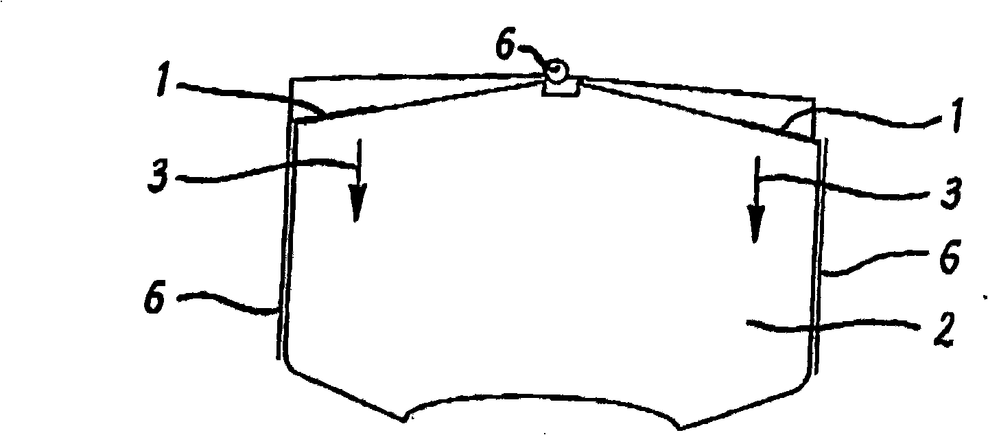
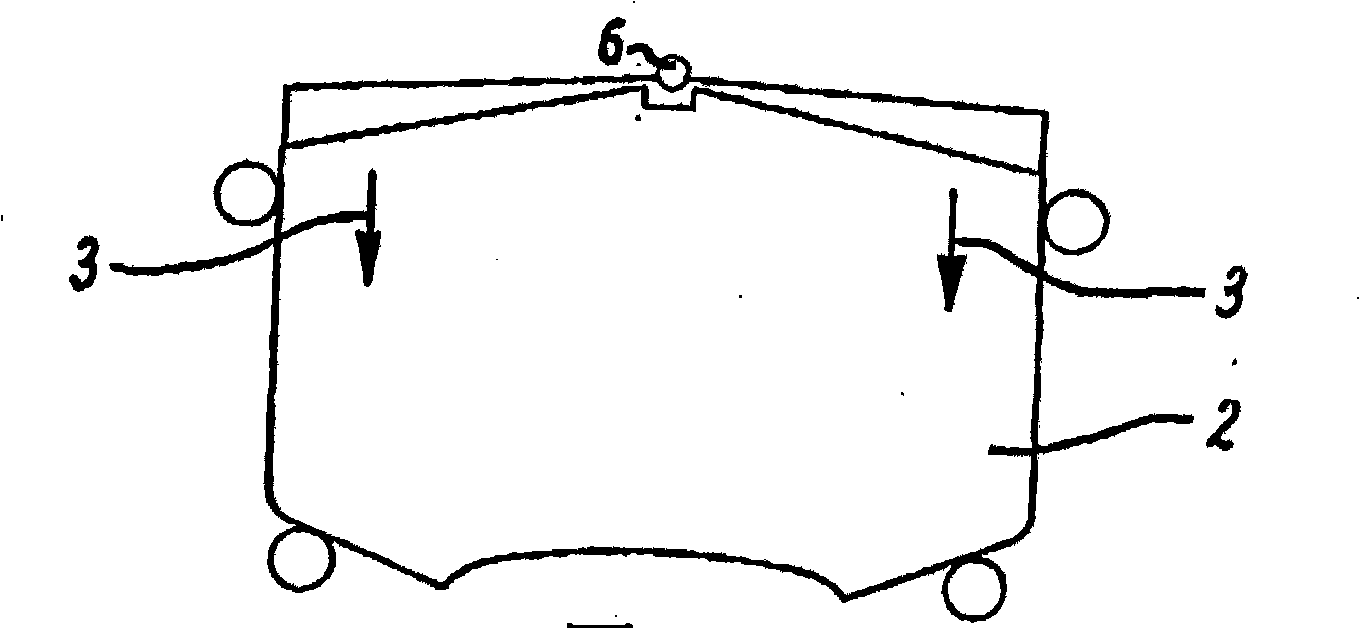
[0009] 1-8 illustrate various known pad retaining arrangements for a caliper of a disc brake of a vehicle. In all cases, a conventional push spring urges the liner in a downward direction identified in each case as arrow 3, wherein the conventional push spring is identified as 1 throughout Figures 1-8 and the liner is throughout Figures 1-8. 8 is identified as 2. Springs mounted on the centrally located pivot 6 act in each case on the front and rear ends of the pads in the same downward direction. Other known devices use conventional lift springs which act in an upward rather than downward direction in the same way as push springs. In Figures 1, 2, 3, 4, 6, 7 and 8, elongated cylindrical pins extending at an angle perpendicular to the plane of the pad and its backing plate are arranged at spaced intervals around the perimeter of the pad . exist Figure 5 In the arrangement of , the plate abutment extends alongside the liner, yet is slightly spaced from the liner.

[0010]...


PUM


Abstract

A pad retention device for a brake calliper for a disc brake for a vehicle comprises four spaced elongate cylindrical abutment pins (11) to (14) dispersed at spaced intervals around the periphery of the pad (10). The pins comprise two leading edge pins (11) and (12) and two trailing edge pins (13) and (14). Pin (13) is disposed adjacent the upper leading edge and a further pin (15) provides a centre locating and retaining pin which extends through an aperture (16) in the back plate of the pad. A cantilever spring (17) is mounted on pin (15) and pin (13). In use the spring (17) bears down on the pad (10), using pin (13) as a reaction point and centre locating and retaining pin (15) as a pivot, on the trailing edge side of the pin (15). This in turn tends to rotate the pad in an anticlockwise direction reducing or eliminating pad to abutment pin air gaps and therefore pad rattle and pad knock. This arrangement also provides improved squeal noise resistance.

Description

technical field [0001] The invention relates to a pad retaining device for a brake calliper of a disc brake of a vehicle. Background technique [0002] In known brake calipers, the pads are connected to and held in position by cylindrical abutment pins extending at an angle perpendicular to the pads and the back plate. [0003] A disadvantage of calipers with cylindrical abutment pins is that there are two forms of noise, pad knock and pad rattle, which are related to the way the pads are seated in the caliper. Pad strikes result from the pad back plate being forced against the abutment pin when braking. Pad rattling occurs due to pad movement between abutting pins under non-braking conditions. The air gap of the pad to the abutment pin, the positioning of the abutment pin, and the profile of the pad are controlled for pad collision control. Use lift or push anti-knock springs to control pad slap. [0004] The solutions described above often contradict the requirements o...

Claims


Application Information

Patent Timeline
Patent Type & Authority Applications(China)
IPC IPC(8): F16D65/095F16D55/00F16D65/00F16D65/097
CPCF16D65/0006F16D2055/007F16D65/0978F16D65/0977F16D65/095F16D65/097
Inventor M·斯科特
Owner BENTLEY MOTORS
Why Eureka
Try Eureka