Marking head and marking device using the same

A scribing head and scribing groove technology, which is used in fine working devices, glass cutting devices, glass manufacturing equipment, etc., can solve problems such as scribing groove bending

Inactive Publication Date: 2010-11-03
MITSUBOSHI DIAMOND IND CO LTD
View PDF8 Cites 2 Cited by
  • Summary
  • Abstract
  • Description
  • Claims
  • Application Information

AI Technical Summary

Problems solved by technology

When the cutter wheel deviates from the predetermined line forming the scribed groove, due to the effect of the foot cutter wheel, ther

Method used


Image

  • Marking head and marking device using the same
  • Marking head and marking device using the same
  • Marking head and marking device using the same

Examples


Embodiment Construction

[0064] (Embodiment 1)

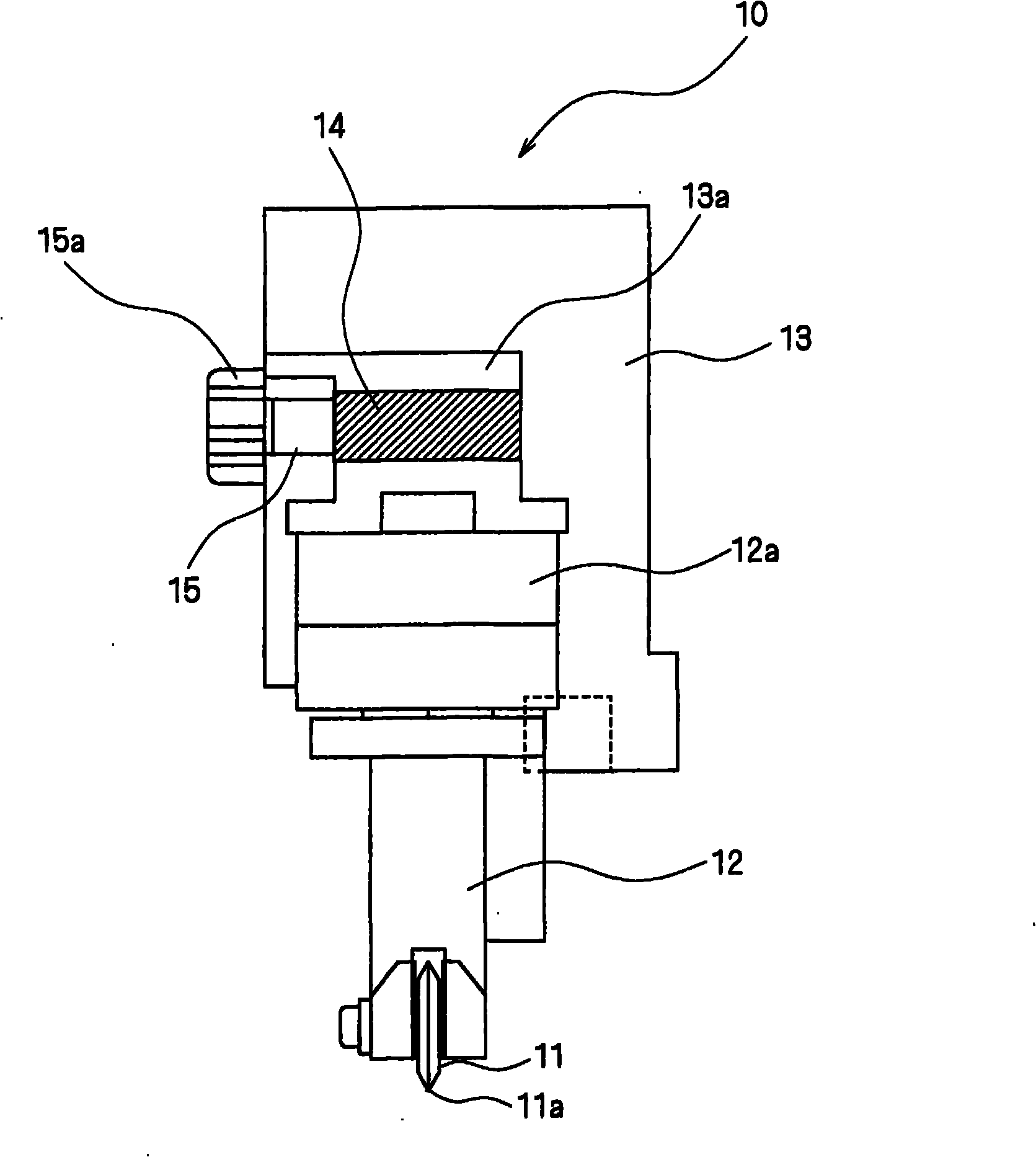
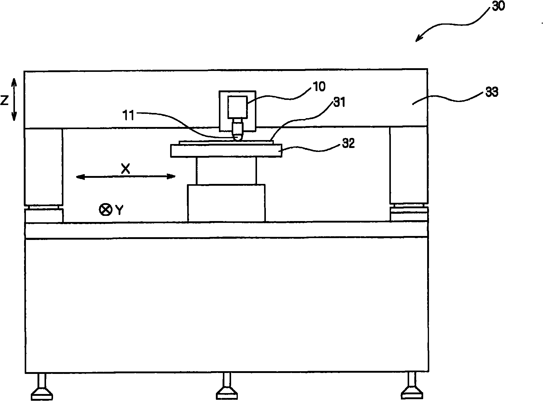
[0065] figure 2 A side view showing a schematic configuration of a scribing head according to Embodiment 1 of the present invention. also, image 3 A front view of a scribing device using the scribing head according to Embodiment 1 of the present invention.

[0066] First, for figure 2 Description of the scribing device for the scribing head shown. Such as image 3 As shown, the scribing device 30 is provided with a support table 32 that supports a brittle material 31 and can be moved. Support table 32 can be in X direction (to image 3 The left and right direction of the paper surface) and the Y direction (to image 3 The vertical direction of the paper surface) moves the brittle material 31 . Moreover, the scribing device 30 is provided with the scribing head 10 on the bridge part 33 which straddles the support table 32 in the X direction. The scribe head 10 is in the Z direction of the brittle material 31 forming the scribe groove (for i...


PUM


Abstract

The invention provides a marking head and a marking device using the same, capable of easily exchanging a keeping tool joint part, keeping the free rotation state of a keeping tool and keeping the state of the keeping tool joint part of fixing the keeping tool, fixing the keeping tool joint part along the preset direction to form a marking groove. The marking head 10 comprises: a cutter wheel 11 bear down on a fragile material to form the marking groove; a keeping tool joint part 12 for mounting the cutter wheel 11 on the direction of the marking groove to rotate; a keeping tool 13 for keeping a rotation axle 12a of the keeping tool joint part 12 along the direction approximately vertical to the surface of the fragile material. The keeping tool 13 comprises: a rotation stop means for stopping the rotation of the rotation axle 12a of the keeping tool joint part 12; a rotation switch means for switching the rotation stop means to switch the rotation stop state of the rotation axle and the rotation free state of the rotation axle.

Description

technical field [0001] The invention relates to a scribing head for forming scribing grooves on brittle materials and a scribing device using the scribing head. Background technique [0002] In the conventional scribing device, the scribing head, which is held by the holder with the cutter wheel at the front end so as to be freely rotatable in a direction approximately perpendicular to the surface of the brittle material, moves up and down on the surface of the brittle material. The brittle material moves relative to the scribing head, and a scribe groove is formed on the surface of the brittle material (see Patent Document 1). In addition, the center position of the rotary shaft of the cutter wheel is arranged on the scribing head so that it is not located on the axis line of the rotary shaft of the joint part of the holder to produce the effect of the caster wheel and improve the straightness of the cutter wheel. [0003] However, in the case where the joint of the holder...

Claims


Application Information

Patent Timeline
IPC IPC(8): B28D5/00
CPCB26D3/085C03B33/027C03B33/033C03B33/10
Inventor 冈岛康智
Owner MITSUBOSHI DIAMOND IND CO LTD
Why Eureka
Try Eureka