Module marking and identifying method, terminal and module thereof

A module and terminal technology, which is applied in the direction of induction recording carrier, telephone communication, network data management, etc., can solve the problems of device performance degradation, affecting product customer experience, etc., and achieve the effect of saving system resources

Active Publication Date: 2012-04-25
HUAWEI DEVICE CO LTD
View PDF4 Cites 0 Cited by
  • Summary
  • Abstract
  • Description
  • Claims
  • Application Information

AI Technical Summary

Problems solved by technology

[0005] For different module processes, using the same parameters for configuration will lead to device performance degradation and affect the customer experience of the product; in addition, the existing design scheme cannot realize the identification of module manufacturers using different Driver ICs or Sensors

Method used


Image

  • Module marking and identifying method, terminal and module thereof
  • Module marking and identifying method, terminal and module thereof
  • Module marking and identifying method, terminal and module thereof

Examples


Embodiment 1

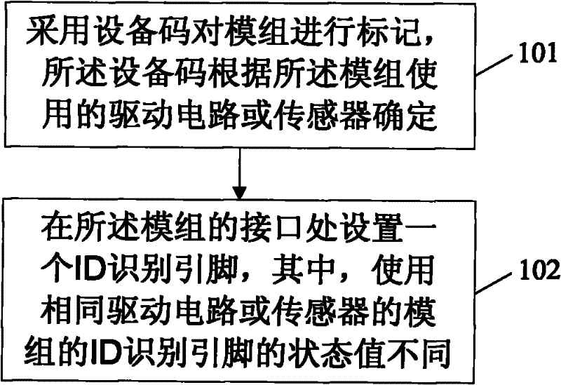
[0032] An embodiment of the present invention provides a module marking method, such as figure 1 As shown, the module marking method includes:

[0033] 101. Use an equipment code to mark the module, and the equipment code is determined according to the driving circuit or sensor used by the module;

[0034] Wherein, the device code is located in the register of the driving circuit or sensor used by the module, and the device codes of the modules using different driving circuits or sensors are different, and the module selects a driving circuit or sensor, and the The device code of the module can be determined.

[0035] 102. Set an ID identification pin at the interface of the modules, wherein the state values ​​of the ID identification pins of the modules using the same drive circuit or sensor are different.

[0036] In the module marking method of the embodiment of the present invention, an ID identification pin is set at the interface of the module, wherein the state values...

Embodiment 2

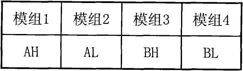
[0038] An embodiment of the present invention provides a module identification method. like figure 2 As shown, in this embodiment, there are four modules, each from different module manufacturers, and every two modules use the same Driver IC or Sensor, wherein, module 1 and module 2 use IC A , module 3 and module 4 use IC B. An ID identification pin is assigned at the interface of each module, where two modules using the same Driver IC or Sensor are assigned ID states as "H" and "L" respectively, thus forming four different states Combinations of: AH, AL, BH, BL.

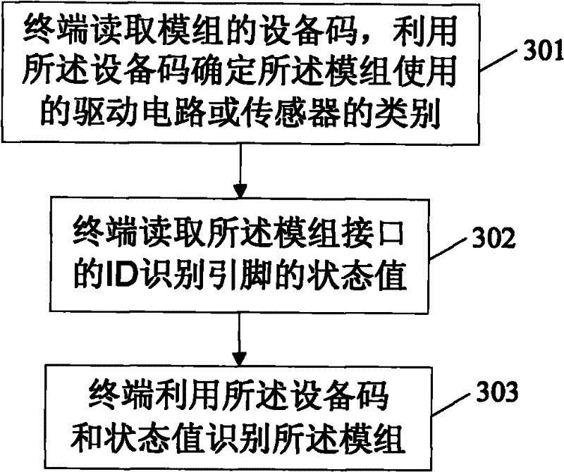
[0039] like image 3 As shown, the module identification method includes:

[0040] 301. The terminal reads the device code of the module, and uses the device code to determine the type of the drive circuit or sensor used by the module;

[0041] Wherein, the terminal can read the device code of the module through the software located in the terminal. Of course, the method for the terminal to read the device cod...

Embodiment 3

[0053] The embodiment of the present invention provides a module, such as Figure 4 As shown, the modules include:

[0054] The equipment code marking module 401 is used to mark the module with the equipment code, and the equipment code is determined according to the driving circuit or sensor used by the module; wherein, the equipment code is located in the driving circuit or the sensor used by the module In the register of the sensor, the device codes of the modules using different driving circuits or sensors are different;

[0055] The state value marking module 402 is configured to set an ID identification pin at the interface of the module, wherein the state values ​​of the ID identification pins of the modules using the same drive circuit or sensor are different.

[0056] In the module of the embodiment of the present invention, an ID identification pin is set at the interface of the module, wherein the state values ​​of the ID identification pins of the modules using th...


PUM


Abstract

The embodiment of the invention discloses a module marking and identifying method, a terminal and a module thereof. The module marking and identifying method comprises adopting a device code which is determined by a driving circuit or a transducer used by the module to mark the module, arranging an ID identification pin at the interface of the module, wherein, the state values of the ID identification pin of the module using the identical driving circuit or transducer are different. The module identifying method comprises: reading the device code of the module, and judging the category of thedriving circuit or transducer used by the module according to the device code; reading the state values of the ID identification pin at the interface of the module; and using the device code and the state values to indentify the module. The invention can be applied to identification on different module factories.

Description

technical field [0001] The invention relates to the field of terminal technology, in particular to a module marking and identification method, a terminal and a module thereof. Background technique [0002] At present, among the peripheral devices attached to mobile phones, the same type of devices may use different IC chip and module processes. For peripherals such as LCD and Camera that require software configuration, even if the Driver IC or Sensor is the same, the characteristics of the devices produced by different module manufacturers are different. In order to maximize the effect of the device, it is necessary to configure the parameters of each manufacturer's device separately. One problem brought about by the separate parameter configuration is how to identify the module manufacturer. [0003] Existing design schemes generally require that the Driver IC or Sensor models used by peripheral devices be consistent, and adapt to different module processes by finding a se...

Claims


Application Information

Patent Timeline
Patent Type & Authority Patents(China)
IPC IPC(8): H04W8/20H04M1/725G06K7/00H04M1/72409
Inventor 侯靖波
Owner HUAWEI DEVICE CO LTD
Why Eureka
Try Eureka