Compound eye imaging device, distance measurement device, parallax calculation method and distance measurement method
A camera device, compound eye technology, applied in the direction of measuring distance, measuring device, using optical device, etc., can solve the problems of estimation error, non-symmetrical object, parallax estimation error, etc.
- Summary
- Abstract
- Description
- Claims
- Application Information
AI Technical Summary
Problems solved by technology
Method used
Image
Examples
Embodiment 1
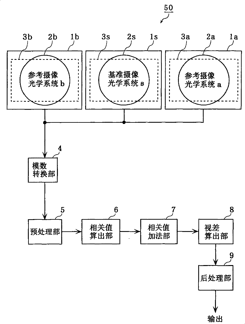
[0155] figure 1 It is a diagram showing the configuration of the distance measuring device 50 according to this embodiment. This distance measuring device 50 includes: three cameras 1s, 1a, 1b; an analog-to-digital conversion unit 4; a preprocessing unit 5; a correlation value calculation unit 6; a correlation value addition unit 7; a parallax calculation unit 8;
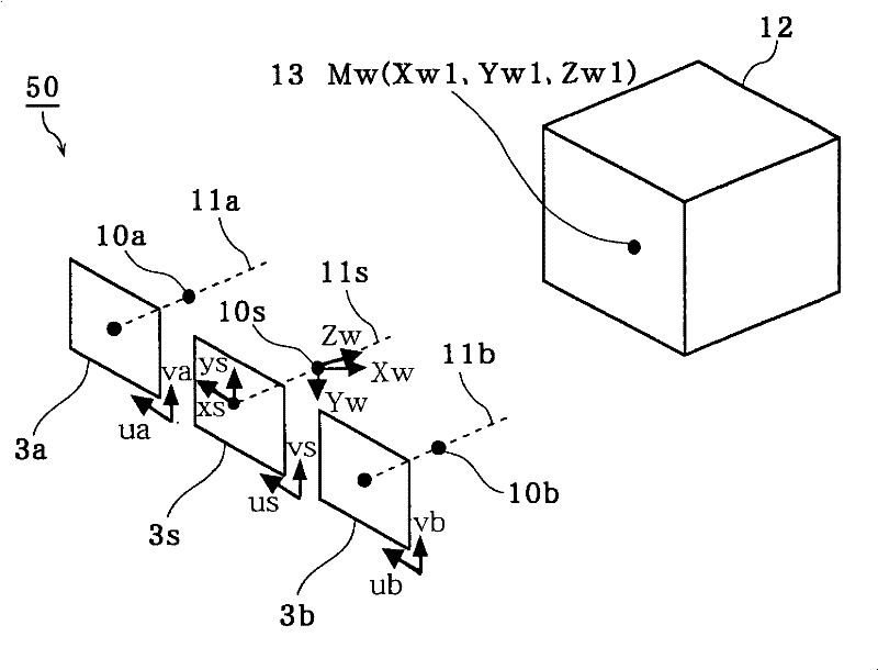
[0156] The three cameras 1s, 1a, and 1b each have the same structure. That is, the camera 1s includes a lens 2s and an imaging area 3s, the camera 1a includes a lens 2a and an imaging area 3a, and the camera 1b includes a lens 2b and an imaging area 3b. Here, the camera 1s is called a reference imaging optical system s, the camera 1a is called a reference imaging optical system a, and the camera 1b is called a reference imaging optical system b.
[0157] The imaging regions 3s, 3a, and 3b are formed, for example, on solid-state imaging devices such as CCDs and CMOSs, and generate images based on light of objects ...
Embodiment 2
[0216] Next, a distance measuring device according to Embodiment 2 of the present invention will be described.
[0217] The distance measuring device 60 according to the present embodiment is different from the distance measuring device 50 of the first embodiment in that the preprocessing unit 5 includes a smoothing filter unit for reducing the high-frequency components of the image. However, other components and functions are the same as those of the first embodiment. 1 distance measuring device 50 is the same. Therefore, the description will focus on the characteristic parts of the distance measuring device of this embodiment.
[0218] Figure 10 It is a diagram showing the configuration of the distance measuring device 60 according to the present embodiment. In addition, the same components as those in the first embodiment are denoted by the same reference numerals, and description thereof will be omitted.
[0219] As shown in the figure, the preprocessing unit 5 include...
Embodiment 3
[0227] Next, a distance measuring device according to Embodiment 3 of the present invention will be described.
[0228] Figure 13 It is a diagram showing the configuration of the distance measuring device 70 according to this embodiment. Such as Figure 13 Shown, the optical center 19b of the reference imaging optical system b, for the straight line connecting the optical center 19s of the reference imaging optical system s and the optical center 19a of the reference imaging optical system a Figure 13 dashed line 18), separated by a distance Error_v in the vertical direction of the dashed line 18. That is, the distance measuring device 70 has an error in the optical center position (hereinafter referred to as a baseline vertical error) Error_v. In addition, there is a difference of Error_h between the base length Ba which is the distance between the optical center 19s and the optical center 19a, and the base length Bb (distance in the direction parallel to the dotted line...
PUM
 Abstract
Description
Claims
Application Information
 - R&D
- Intellectual Property
- Life Sciences
- Materials
- Tech Scout
- Unparalleled Data Quality
- Higher Quality Content
- 60% Fewer Hallucinations
Browse by: Latest US Patents, China's latest patents, Technical Efficacy Thesaurus, Application Domain, Technology Topic, Popular Technical Reports.
© 2025 PatSnap. All rights reserved.Legal|Privacy policy|Modern Slavery Act Transparency Statement|Sitemap|About US| Contact US: help@patsnap.com


