Compound eye imaging device, distance measurement device, parallax calculation method and distance measurement method

A camera device, compound eye technology, applied in the direction of measuring distance, measuring device, optical device, etc., can solve problems such as asymmetrical objects, estimation errors, parallax estimation errors, etc.

Active Publication Date: 2010-03-24
PANASONIC INTELLECTUAL PROPERTY CORP OF AMERICA
View PDF1 Cites 16 Cited by
  • Summary
  • Abstract
  • Description
  • Claims
  • Application Information

AI Technical Summary

Problems solved by technology

Therefore, there is a problem that the transition of the correlation value does not become a symmetrical object based on the actual parallax, and an estimation error of the parallax occurs.
and, for example Figure 40A as well as Figure 40B The same is true for the shown multi-eye stereo camera using three or more optical systems. There is a problem in that the transition of the correlation value is not symmetrical with respect to the actual parallax, and an estimation error of the parallax occurs.

Method used


Image

  • Compound eye imaging device, distance measurement device, parallax calculation method and distance measurement method
  • Compound eye imaging device, distance measurement device, parallax calculation method and distance measurement method
  • Compound eye imaging device, distance measurement device, parallax calculation method and distance measurement method

Examples


Embodiment 1

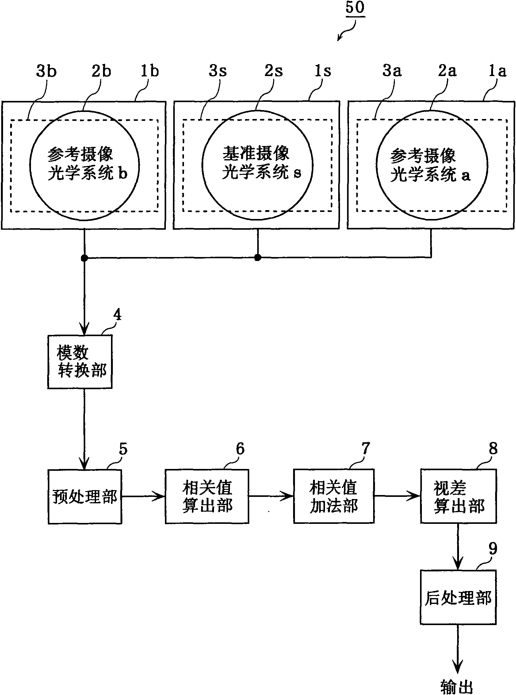
[0155] figure 1 It is a diagram showing the configuration of the distance measuring device 50 according to this embodiment. This distance measuring device 50 includes: three cameras 1s, 1a, 1b; an analog-to-digital conversion unit 4; a preprocessing unit 5; a correlation value calculation unit 6; a correlation value addition unit 7; a parallax calculation unit 8;

[0156] The three cameras 1s, 1a, and 1b each have the same structure. That is, the camera 1s includes a lens 2s and an imaging area 3s, the camera 1a includes a lens 2a and an imaging area 3a, and the camera 1b includes a lens 2b and an imaging area 3b. Here, the camera 1s is called a reference imaging optical system s, the camera 1a is called a reference imaging optical system a, and the camera 1b is called a reference imaging optical system b.

[0157] The imaging regions 3s, 3a, and 3b are formed, for example, on solid-state imaging devices such as CCDs and CMOSs, and generate images based on light of objects ...

Embodiment 2

[0216] Next, a distance measuring device according to Embodiment 2 of the present invention will be described.

[0217] The distance measuring device 60 according to the present embodiment is different from the distance measuring device 50 of the first embodiment in that the preprocessing unit 5 includes a smoothing filter unit for reducing the high-frequency components of the image. However, other components and functions are the same as those of the first embodiment. 1 distance measuring device 50 is the same. Therefore, the description will focus on the characteristic parts of the distance measuring device of this embodiment.

[0218] Figure 10 It is a diagram showing the configuration of the distance measuring device 60 according to the present embodiment. In addition, the same components as those in the first embodiment are denoted by the same reference numerals, and description thereof will be omitted.

[0219] As shown in the figure, the preprocessing unit 5 include...

Embodiment 3

[0227] Next, a distance measuring device according to Embodiment 3 of the present invention will be described.

[0228] Figure 13 It is a diagram showing the configuration of the distance measuring device 70 according to this embodiment. Such as Figure 13 Shown, the optical center 19b of the reference imaging optical system b, for the straight line connecting the optical center 19s of the reference imaging optical system s and the optical center 19a of the reference imaging optical system a Figure 13 dashed line 18), separated by a distance Error_v in the vertical direction of the dashed line 18. That is, the distance measuring device 70 has an error in the optical center position (hereinafter referred to as a baseline vertical error) Error_v. In addition, there is a difference of Error_h between the base length Ba which is the distance between the optical center 19s and the optical center 19a, and the base length Bb (distance in the direction parallel to the dotted line...


PUM


Abstract

This object aims to provide a compound eye imaging device that makes it possible to estimate a sub-pixel parallax with a high degree of precision regardless of a brightness distribution of the front surface of an object. A compound eye imaging device is provided with a standard imaging optical system to generate an image including a standard image and not-less-than-two and even number reference imaging optical systems arranged in a substantially point symmetry with respect to the standard imaging optical system for generating images including a reference image, wherein each of the not-less-than-two and even number reference imaging optical systems is comprised of a correlation value calculation unit (6) that calculates a correlation value for every shifted amount in the case where one of the reference images is shifted in respect of the standard image along a direction in parallel with a base line, a correlation value adding unit (7) that adds the correlation value calculated for eachof the not-less-than-two and even number reference imaging optical systems at every corresponding shifted value so as to calculate a resultant correlation value, and a parallax calculation unit (8) that calculates parallax that is the maximum shifted value at a level of the sub-pixel in the degree of similarity between the standard image and the reference image in accordance with the resultant correlation value.

Description

technical field [0001] The present invention relates to a compound eye imaging device and the like which have a plurality of imaging optical systems and calculate parallax generated between the imaging optical systems. Background technique [0002] In recent years, there has been an increasing need to measure the distance from a predetermined position to an object, or the three-dimensional position (shape) of the object. For example, a method has been proposed for assisting the angle of view of a car, that is, not only displaying images of surrounding objects captured by a small camera mounted on the car, but also displaying the correct distance between the object and the car measured by a distance measuring device. distance information to accurately avoid collisions with surrounding objects. In addition, in mobile phones, televisions, and the like, in order to more faithfully reproduce the realism of video, a stereoscopic video input / output device is required. High precis...

Claims


Application Information

Patent Timeline
Patent Type & Authority Applications(China)
IPC IPC(8): G01C3/06G01B11/00G06T1/00H04N5/225H04N13/239
CPCG06T2207/30041H04N5/2254H04N13/0239G06T7/0077G01C3/085G06T2207/10012G06T7/596H04N13/239
Inventor 大山一朗
Owner PANASONIC INTELLECTUAL PROPERTY CORP OF AMERICA
Why Eureka
Try Eureka