Power tool with slidable storage device

A technology for storage devices and power tools, which is applied in the field of power tools and can solve the problems of unsafe injuries and easy grinding of hands

Inactive Publication Date: 2010-03-31
叶世祯
View PDF0 Cites 14 Cited by
  • Summary
  • Abstract
  • Description
  • Claims
  • Application Information

AI Technical Summary

Problems solved by technology

It is easy to grind your hands when holding the chuck with your hands, which is very unsafe to cause injuries.

Method used


Image

  • Power tool with slidable storage device
  • Power tool with slidable storage device
  • Power tool with slidable storage device

Examples


Embodiment Construction

[0033] Regarding the technology, means and effects used in the present invention, a preferred embodiment is given and described in detail below with drawings, which are for illustration purposes only, and are not limited by this structure in the patent application.

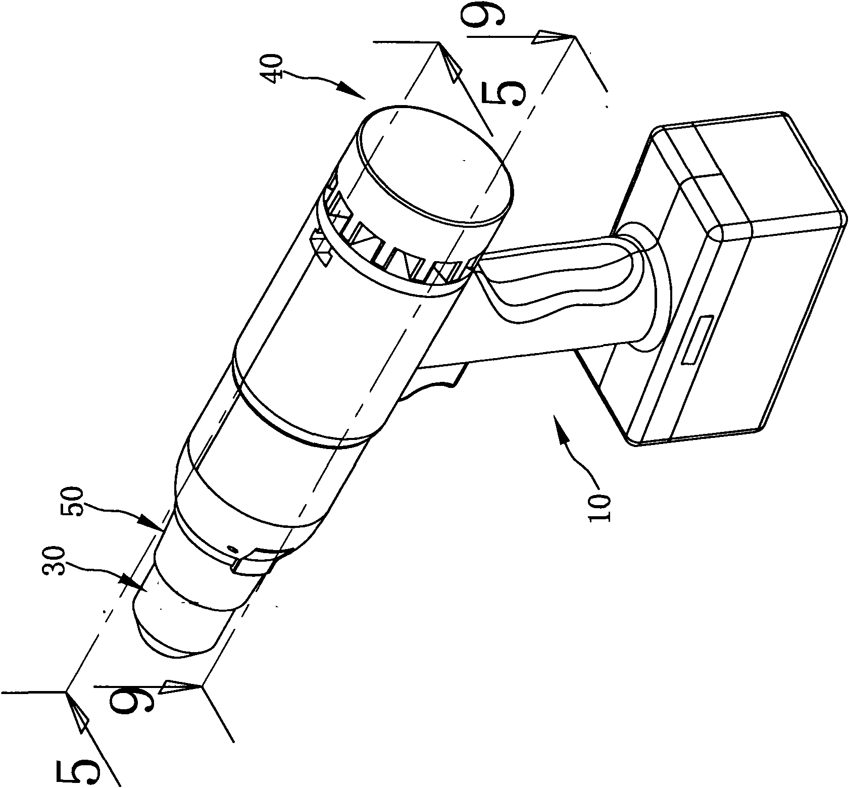
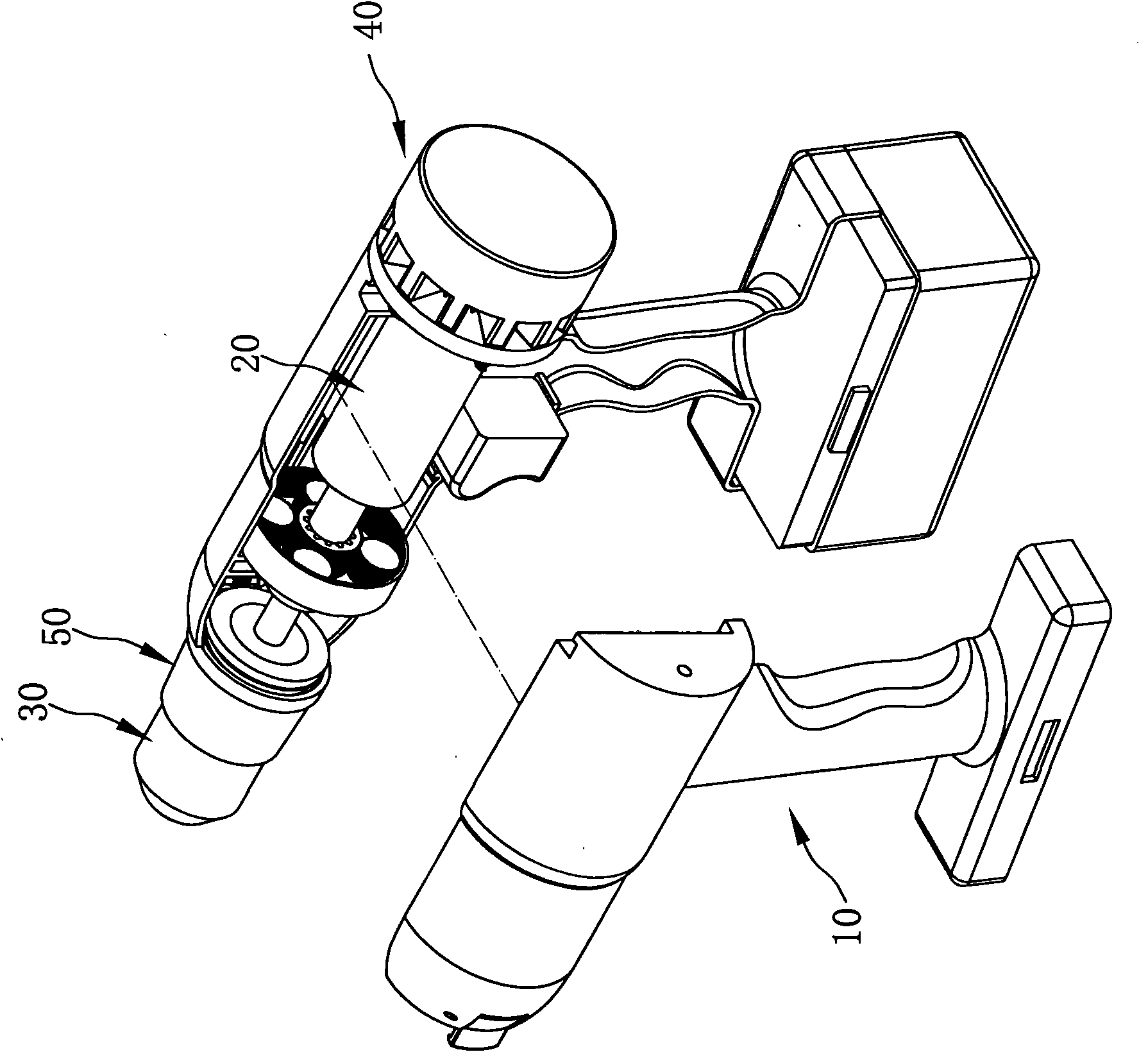
[0034] Please refer to figure 1 as well as figure 2 , is a three-dimensional appearance diagram and an internal schematic diagram of the present invention. The present invention includes a housing 10, a driving device 20, a chuck device 30, a storage device 40 and an elastic device 50, and the driving device 20 is installed in the described Inside the housing 10, it is used to provide power. The collet device 30 is arranged at the front end of the housing 10 and is connected with the driving device 20 . The storage device 40 is slidably disposed on the housing 10 to selectively provide tool bits to the collet device 30 .

[0035] Please refer to image 3 as well as Figure 4 , the housing 10 forms a front and...


PUM


Abstract

The invention relates to a power tool with a slidable storage device, which comprises a shell, a driving device, a collet device and a storage device, wherein the shell forms a forward and backward accommodating space, and a handle part extends from one side of the shell; the driving device is arranged in the accommodating space; the collet device is arranged in the front end of the shell ; the storage device is slidably arranged in the shell in a radial direction and holds a tool head; and the storage device can be moved between a first position and a second position; when located at the first position, the tool head of the storage device can be moved to the collet device; and when located at the second position, the tool head of the storage device is restricted in the storage device.

Description

technical field [0001] The present invention relates to power tools, and more particularly to a power tool having a slidable storage device for selectively providing tool bits. Background technique [0002] Rotary power tools can achieve sufficient speed and relative torque by manually changing the gear of the reduction mechanism to provide multi-stage variable speed and relative torque for hammer drilling, drilling, variable speed and bidirectional rotation. [0003] It is very inconvenient to store, retrieve and install tool heads with different specifications in existing power tools. Not only that, when the existing power tool wants to lock the tool head, it is necessary to hold the chuck at the front end by hand to limit its rotation, and then press the trigger to clamp or loosen the tool head. It is easy to grind hands when holding the chuck with hands, which is very unsafe to cause injuries. For the problems referred to above, there is an urgent need for improvement....

Claims


Application Information

Patent Timeline
IPC IPC(8): B25F5/00B25F5/02
Inventor 叶世祯
Owner 叶世祯
Why Eureka
Try Eureka