Testable integrated circuit and test method

An integrated circuit and circuit technology, applied in the direction of circuits, measuring electricity, measuring electrical variables, etc., can solve the problem that the on-chip comparator cannot reach the accuracy level, and does not consider that the switch group has a first switch with a first size and a second switch. Two-size second switch, high resistance problems

Inactive Publication Date: 2010-03-31
NXP BV
View PDF0 Cites 8 Cited by
  • Summary
  • Abstract
  • Description
  • Claims
  • Application Information

AI Technical Summary

Problems solved by technology

[0006] The disadvantage of this approach is that the on-chip comparators are not capable of the required level of accuracy to detect specific resistive defects in such switches
Furthermore, this method does not take into account that the switch group has a first switch with a first size and a second switch with a second size, and that a defect-free first switch has a higher resistance than a defect-free second switch

Method used


Image

  • Testable integrated circuit and test method
  • Testable integrated circuit and test method
  • Testable integrated circuit and test method

Examples


Embodiment Construction

[0029] It should be understood that the drawings are only schematic and not drawn to scale. It should also be understood that the same reference numerals are used throughout the drawings to designate the same or similar parts.

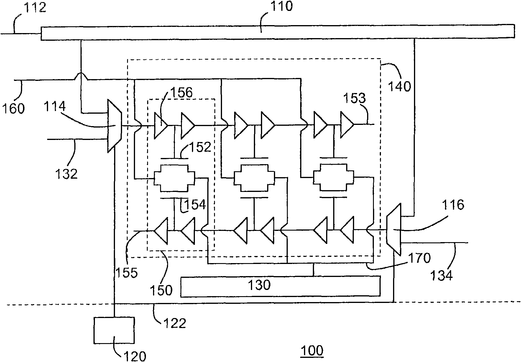
[0030] exist figure 1 In , a portion of an IC 100 according to the present invention is shown. Circuit portion 130 has internal supply rail 170 coupled to global supply rail 160 via group 140 of first size switch 152 and second size switch 154 . exist figure 1 In the illustrated embodiment, cluster 140 has three fields 150 , each field including a first size switch 152 and a second size switch 154 . The first size 152 switch has a greater resistance than the second size switch 154 to facilitate gradual power up of the circuit portion 130 . During power-up, the first switch 152 is first turned on so that the circuit portion 130 reaches a specific voltage level, such as V dd / 3, after that, the second switch 154 is turned on to complete the power-on...


PUM


Abstract

An integrated circuit (100) is disclosed comprising a plurality of circuit portions (130), each of the circuit portions having an internal supply rail (170) coupled to a global supply rail (160) via acluster (140) of switches (152; 154) coupled in parallel between the internal supply rail (170) and the global supply rail (160). Each cluster (140) of switches (152; 154) has a first switch (152) having a first size and a second switch (154) having a second size, a fault-free first switch (152) having a higher resistance than a fault-free second switch (154). The IC (100) further comprises a test arrangement for testing the respective clusters (140) of switches (152; 154) in a test mode. The test arrangement comprises a test control input; a test output coupled to the respective internal supply rails (170) and control means (110, 114, 116) coupled to the test control input for enabling a selected cluster (140) of switches (152; 154) in the test mode. The control means comprise first selection means (114) for selectively enabling the first switch (152) and second selection means (116) for selectively enabling the second switch (154) of the selected cluster (140) in the test mode. Thisarrangement allows for the accurate measurement of the resistance of power switches (152; 154) between a global power rail (160) and an internal power rail (170) of a circuit portion (130), thus facilitating the detection of both resistive and stuck-at faults in these switches (152; 154).

Description

technical field [0001] The present invention relates to an integrated circuit (IC) comprising a plurality of circuit portions each having an internal supply rail coupled to a global supply rail via a switch bank connected in parallel between the internal supply rail and the global supply rail coupled, and the supply input is coupled to the global supply rail. [0002] The invention also relates to methods for testing such ICs. Background technique [0003] Continuing advances in IC design and production have led to the fabrication of very large-scale integrated (VLSI) ICs that can perform many different functions and include millions of devices (eg, transistors), which can be organized into distinct circuit segments , each circuit part implements at least a part of IC-specific functions. Such ICs tend to dissipate a considerable amount of power, which can cause many problems. For example, at peak consumption, the power demands of various circuit parts may exceed the capab...

Claims


Application Information

Patent Timeline
Patent Type & Authority Applications(China)
IPC IPC(8): G01R31/317H01L23/50
CPCG01R31/31715
Inventor 劳伦·苏埃夫埃曼努埃尔·艾里
Owner NXP BV
Why Eureka
Try Eureka