Image pickup device and image pickup method

A camera device and image technology, applied in image communication, TV, color TV components and other directions, can solve problems such as unnatural colors, and achieve the effect of low noise

Active Publication Date: 2010-03-31
HANGZHOU HIKVISION DIGITAL TECH
View PDF3 Cites 15 Cited by
  • Summary
  • Abstract
  • Description
  • Claims
  • Application Information

AI Technical Summary

Problems solved by technology

[0014] As mentioned above, flash irradiation can solve the problem...

Method used


Image

  • Image pickup device and image pickup method
  • Image pickup device and image pickup method
  • Image pickup device and image pickup method

Examples


Embodiment 1

[0137] The imaging device of Embodiment 1 is an imaging device capable of photographing a subject having natural colors and shadows even in a dark place where the photographing environment is dark, using a light-emitting unit such as a strobe together with observed color information.

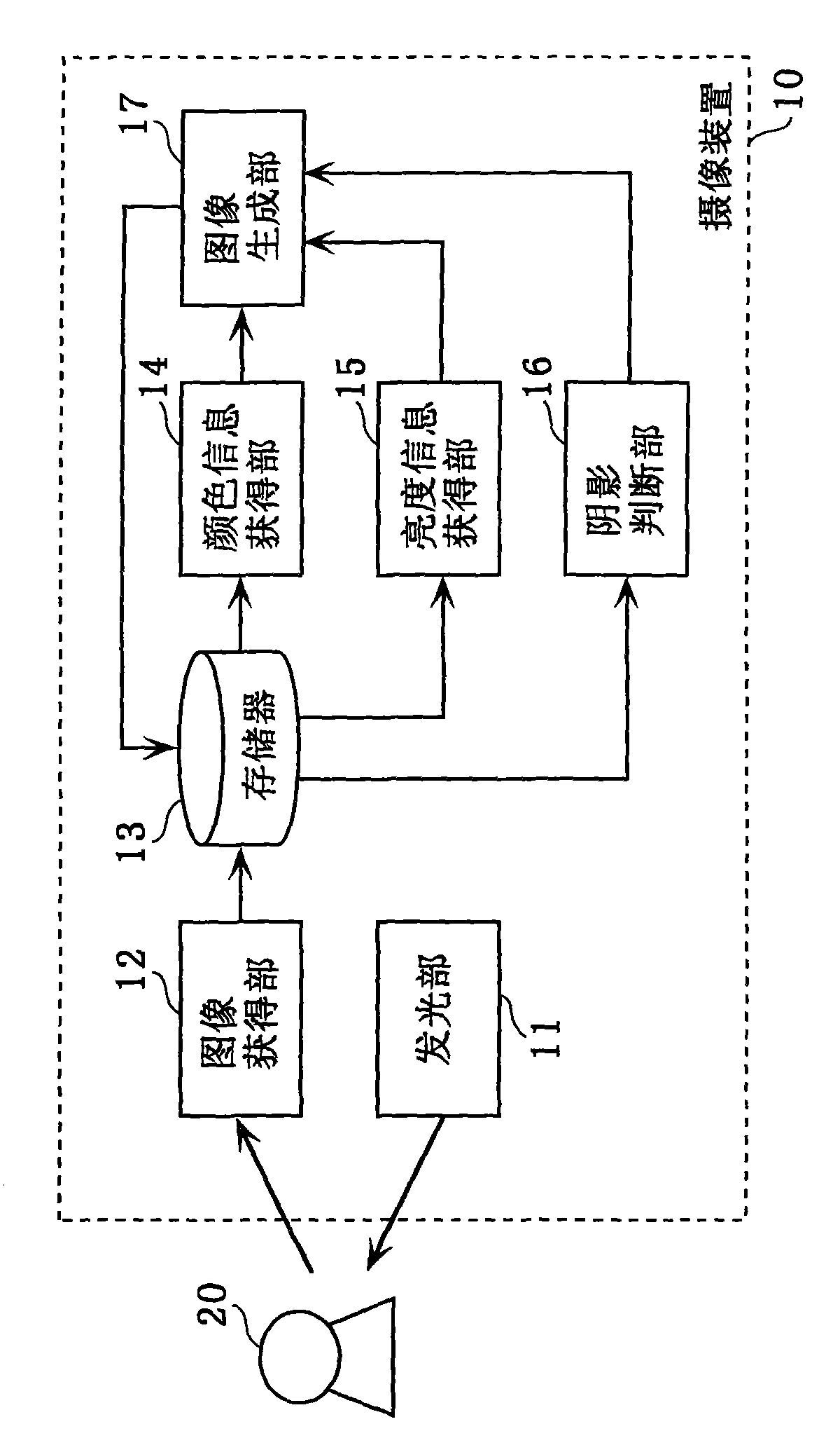
[0138] figure 1 It is a block diagram showing an example of the configuration of the imaging device 10 of the first embodiment. As shown in the figure, the imaging device 10 includes a light emitting unit 11 , an image obtaining unit 12 , a memory 13 , a color information obtaining unit 14 , a luminance information obtaining unit 15 , a shadow determining unit 16 , and an image generating unit 17 .

[0139] The light emitting unit 11 emits flash light to illuminate the subject 20 .

[0140] The image acquisition unit 12 captures the subject 20 while the light emitting unit 11 emits flash light, thereby obtaining a continuous shooting image composed of at least two images with different brightn...

Embodiment 2

[0231] In the imaging device of Embodiment 2, when there are a plurality of subjects, the distance of each subject is estimated, and the estimated distance information is used, so that compared with the case where there is no distance information, it is possible to make use of each subject. Synthesis of images with optimal exposure time of the subject.

[0232] Figure 9 It is a block diagram showing an example of the configuration of the imaging device 30 of the second embodiment. The imaging device 30 in the same figure differs from the imaging device 10 of the first embodiment in that the imaging device 30 further includes a distance obtaining unit 31 and a memory 32 , and includes an image generating unit 34 instead of the image generating unit 17 . Hereinafter, the description of the same parts as in the first embodiment will be omitted, and the differences will be mainly described.

[0233] The distance obtaining unit 31 obtains the distance between the imaging device ...

Embodiment 3

[0281] The imaging device of the third embodiment is an imaging device that obtains continuous shooting images composed of a plurality of images with different luminances by changing the amount of flash light every time an image is obtained when continuously shooting a subject.

[0282] Figure 17 It is a block diagram showing an example of the configuration of the imaging device 50 of the third embodiment. The imaging device 50 in the same figure differs from the imaging device 10 of the first embodiment in that it includes a light emitting unit 51 instead of the light emitting unit 11 and further includes a light emission control unit 52 newly. Hereinafter, the description of the same parts as in the first embodiment will be omitted, and the differences will be mainly described.

[0283] The light emitting unit 51 is a light emitting diode or the like capable of changing the light quantity of the flash. The light emitting unit 51 irradiates the subject 20 with a flash ligh...


PUM


Abstract

Disclosed is an image pickup device that obtains adequate brightness by irradiating flash light, and that acquires an image of colors identical to humanly perceived colors. An image pickup device (10)that irradiates flash light to photograph a subject (20) includes: a light emission unit (11) that irradiates flash light on the subject; an image acquisition unit (12) that acquires a continuously photographed image containing a first image and a second image of higher luminance than the first image by photographing the subject (20) while the flash light is being irradiated by the light emissionunit (11); a color information acquisition unit (14) that acquires the color information of a first color vector from the first image; a luminance information acquisition unit (15) that acquires theluminance information of a second color vector from the second image; and an image generation unit (17) that generates a corrected image of higher luminance than the first image by generating a thirdcolor vector corresponding to the color information of the first color vector and the luminance information of the second color vector.

Description

technical field [0001] The present invention relates to an imaging device and an imaging method capable of capturing the color and shadow of the object when the object is photographed under flashlight illumination as when photographing under natural light. Background technique [0002] In recent years, with the popularization of small electronic cameras, shooting has become more convenient than before. Therefore, photographers carry electronic cameras with them, not only shooting outdoors during the day, but also shooting indoors or at night. Because the outdoors are bright during the day, the shutter speed is fast even in automatic shooting, and you can shoot without having to raise the sensitivity more than necessary. Therefore, an image with less vibration and less noise can be captured. [0003] On the other hand, because the brightness is dark when shooting indoors or at night, it is necessary to slow down the shutter speed to obtain more light, or to increase the sen...

Claims


Application Information

Patent Timeline
IPC IPC(8): H04N9/04
CPCH04N5/2355H04N5/2354H04N9/735H04N23/741H04N23/74H04N23/88
Inventor 石井育规物部祐亮小仓康伸
Owner HANGZHOU HIKVISION DIGITAL TECH
Why Eureka
Try Eureka