
Patsnap Eureka
For R&D, Patsnap Eureka makes reading and utilizing patents & technical documents easy.
Patsnap Eureka AIR
Designed for self-driven R&D workflows. Generate viable solutions, solve complex R&D challenges, empower your innovation with AI.

Patsnap Eureka Materials
Designed for material experts only. Revolutionize your material R&D, from search, analyze, to developing new materials.

TechResearch
Generate reliable direction feasibility study reports for your R&D in just a few steps.

TechSeek
Discover and master advanced knowledge NOW. Basics, ideas, possibilities, all at once.

TechMind
As an expert in R&D Theories, TechMind can generates customized viable solutions instantly.

TechRisk
Analyze your overall solution with one click, know your potential R&D risks in advance.

TechMonitor
Get weekly tech updates, stay abreast of the latest tech innovations and key insights.
Mould dumping gear for automatic plastics soaking equipment
A technology of flipping mechanism and mold, applied in coating and other directions, can solve the problems of high labor intensity and low production efficiency of workers, and achieve the effect of reducing labor intensity of workers, improving production efficiency and ensuring quality
- Summary
- Abstract
- Description
- Claims
- Application Information
AI Technical Summary
Problems solved by technology
Method used
Image

Examples
Embodiment Construction
[0011] The present invention is described in further detail by the following examples.
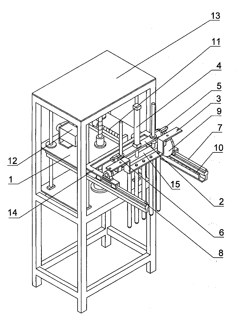
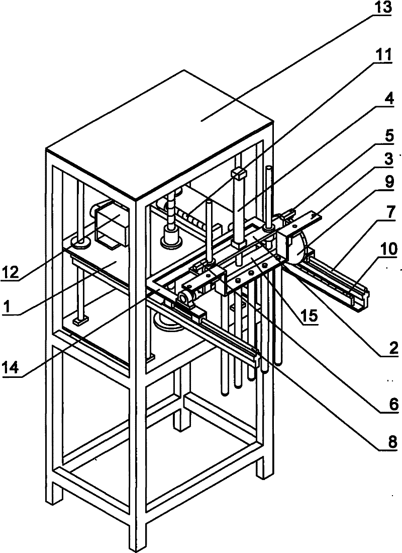
[0012] see figure 1 As shown, a mold turnover mechanism for automatic plastic dipping equipment consists of a lifter frame 13, a base plate 1, a first guide rail 7, a second guide rail 8, a guide rail seat 14, a mold plate 2, a mold 3, a lifting cylinder 4, The 1st rotary cylinder 5, the 2nd rotary cylinder 6, gear 9, rack 10, rotating shaft 15, upper and lower elevating mechanisms on the base plate, guide rail seat 14 front and rear motion drive mechanisms. One end of the first and second guide rails 7 and 8 is respectively connected to the same side of the base plate 1, the guide rail seat 14 is mounted on the first and second guide rails 7 and 8 and connected in a sliding manner, and the mold plate 2 is fixed on the Rail seat 14 both sides. The cross-section of the middle section of the rotating shaft 15 is rectangular, and the piston end of the lifting cylinder 4 installed in the cen...
PUM
 Abstract
Description
Claims
Application Information
 - R&D Engineer
- R&D Manager
- IP Professional
- Industry Leading Data Capabilities
- Powerful AI technology
- Patent DNA Extraction
Browse by: Latest US Patents, China's latest patents, Technical Efficacy Thesaurus, Application Domain, Technology Topic, Popular Technical Reports.
© 2024 PatSnap. All rights reserved.Legal|Privacy policy|Modern Slavery Act Transparency Statement|Sitemap|About US| Contact US: help@patsnap.com