Decentered lens for LED streetlight

An LED street light and eccentric technology, applied in the field of lenses, can solve the problems of short longitudinal illumination distance, unsatisfactory illumination uniformity, and illumination intensity.

Inactive Publication Date: 2010-04-28
SUZHOU ZHONGZE OPTOELECTRONICS TECH
View PDF0 Cites 19 Cited by
  • Summary
  • Abstract
  • Description
  • Claims
  • Application Information

AI Technical Summary

Problems solved by technology

[0002] High-power LED street lamps are being used more and more widely due to their energy saving and long life, and the light distribution technology, which is one of the key and difficult points of LED technology, is becoming more and more important. Various enterprises and scientific and technological workers have spent a lot of energy on exploration and proposed A variety of light distribution methods, currently the most widely used is the optical lens light distribution technology that uses the principle of refraction to distribute light. There are various lens structures, but there is only one purpose, that is, to emit as much light as possible and as uniformly as possible from LED street lights. The area that needs to be illuminated can be irradiated, but the existing light distribution lenses are all axially symmetrical without exception. When they are irradiated vertically, they will form horizontally and vertically symmetrical light spots directly under the lamps. The lighting effect needs to install the lamps in the center of the road, and now the common installation method is to tilt the lamps by 10-20 degrees to move the center of the light spot forward. The distance on the other side is far away, resulting in unsatisfactory uniformity of illumination, especially in road sections where street lights are installed on one side

Method used


Image

  • Decentered lens for LED streetlight
  • Decentered lens for LED streetlight
  • Decentered lens for LED streetlight

Examples


Embodiment Construction

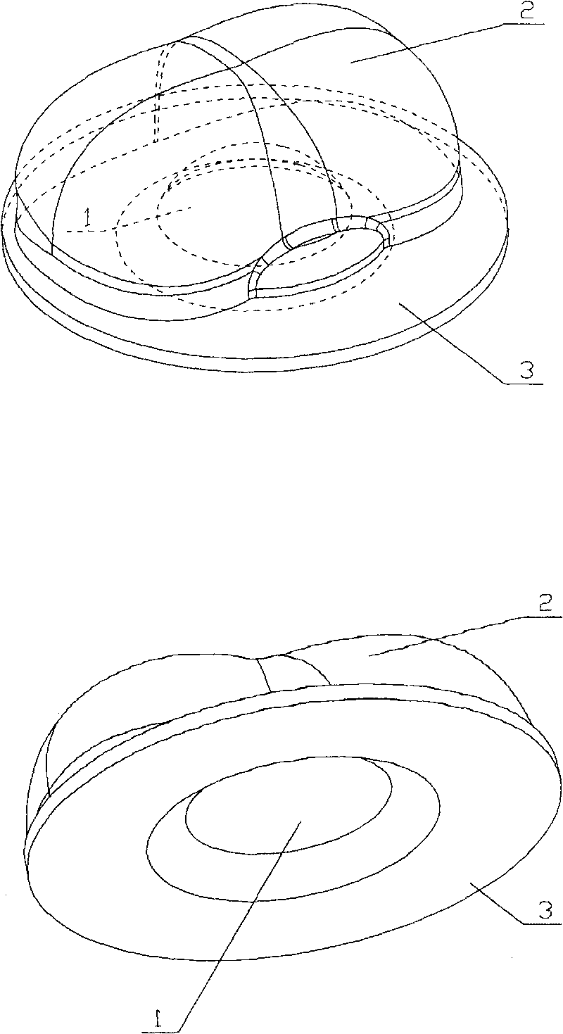
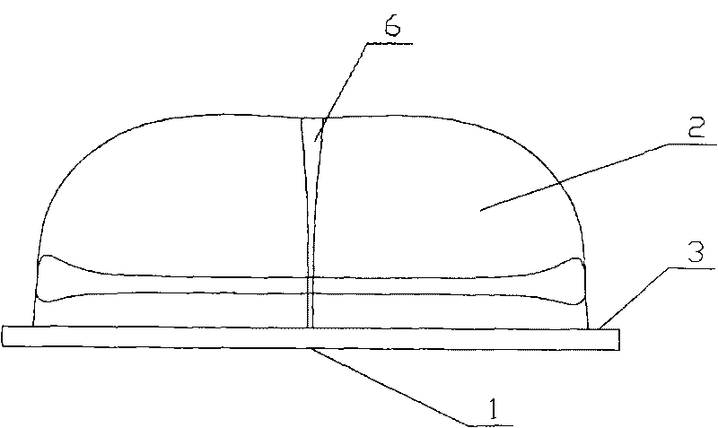
[0022] Such as figure 1 The invention relates to an eccentric lens for an LED street lamp, which consists of a light-incident surface (1), a light-exit surface (2) and a mounting base (3) to form a transparent entity with left-right symmetry and front-back asymmetry.

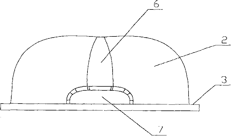
[0023] Such as figure 2 , 3 , 6, 7: The center of the light incident surface is a hemispherical pit (4), and the surroundings of the hemispherical pit are arc-shaped transitional surfaces (5) that are tangent to the hemispherical pit to form a bell mouth. The periphery of the outer plane extends outward to form a circular or elliptical mounting and fixing seat (3), and the opposite surface of the light incident surface is set as the light exit surface (2); Spherical curved surface, the middle part of the curved surface is a concave arc transition surface (6) and an arc-shaped boss (7) is arranged at the intersection of the upper end surface of the mounting and fixing seat, and all parts of the light exit surf...


PUM


Abstract

The invention discloses a decentered lens for an LED streetlight, which is made of glass or resin transparent materials to form a transparent entity by mould pressing and is composed of a light incident face, a light emergent face and an installation fixed seat; the center of the light incident face is a hemispherical pit; the periphery of the hemispherical pit is an arc-shaped transitional surface which forms a flare opening by tangency with the hemispherical pit; the perimeter of the flare opening extends toward an external plane to form a circular or elliptic installation fixed seat; and the opposite surface of the light incident face is arranged as the light emergent face which is composed of eudipleural and forward-backward asymmetric curved faces. The streetlight using the decentered lens can form similar-rectangle or similar-ellipse light spots at one side under the streetlight when irradiating vertically, the ratio of the length to width of the light spot is about 3-4:1, so that more uniform light spot effect can be formed at one side of the road installed with the streetlight of which the illuminance and uniformity can be over 0.7, thus greatly meeting the requirement of road lighting and avoiding the formation of road faces in a spareribs style or a style of sugarcoated haws on a stick.

Description

technical field [0001] The invention relates to a lens, specifically an eccentric lens used for light distribution of high-power LED street lamps. Background technique [0002] High-power LED street lamps are being used more and more widely due to their energy saving and long life, and the light distribution technology, which is one of the key and difficult points of LED technology, is becoming more and more important. Various enterprises and scientific and technological workers have spent a lot of energy on exploration and proposed A variety of light distribution methods, currently the most widely used is the optical lens light distribution technology that uses the principle of refraction to distribute light. There are various lens structures, but there is only one purpose, that is, to emit as much light as possible and as uniformly as possible from LED street lights. The area that needs to be illuminated can be irradiated, but the existing light distribution lenses are all...

Claims


Application Information

Patent Timeline
Patent Type & Authority Applications(China)
IPC IPC(8): F21V5/04F21Y101/02F21W131/103F21Y115/10
CPCF21Y2101/02F21W2131/103F21V5/04F21Y2115/10
Inventor 黄金鹿黄莺缪应明吴海生
Owner SUZHOU ZHONGZE OPTOELECTRONICS TECH
Why Eureka
Try Eureka