A method for non-destructive testing of bolt working load using low-frequency guided waves

A technology of working load and non-destructive testing, which is applied in the direction of measuring force, measuring devices, instruments, etc., to achieve the effects of strong operability, low testing cost and high testing accuracy

Inactive Publication Date: 2011-12-14
BEIJING INSTITUTE OF TECHNOLOGYGY
View PDF0 Cites 0 Cited by
  • Summary
  • Abstract
  • Description
  • Claims
  • Application Information

AI Technical Summary

Problems solved by technology

[0005] The purpose of the present invention is to solve the problem of effectively measuring the working load of the anchor bolt, and propose a method for non-destructive testing of the working load of the anchor using low-frequency guided waves

Method used


Image

  • A method for non-destructive testing of bolt working load using low-frequency guided waves
  • A method for non-destructive testing of bolt working load using low-frequency guided waves
  • A method for non-destructive testing of bolt working load using low-frequency guided waves

Examples


Embodiment 1

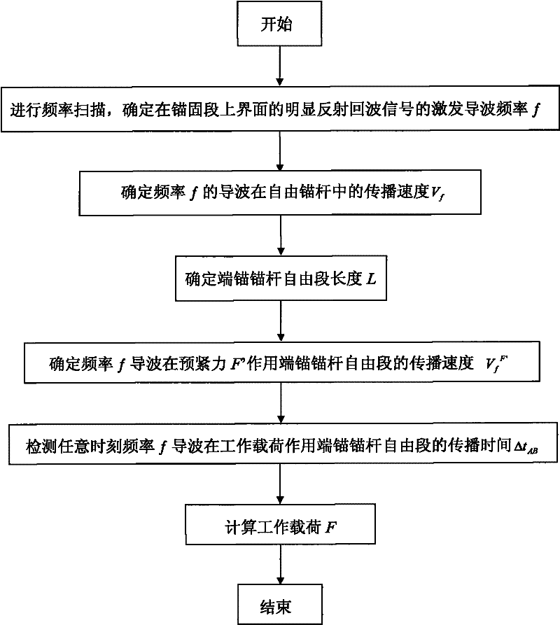
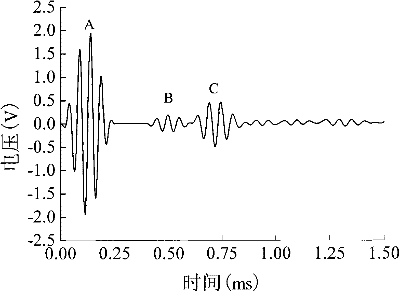
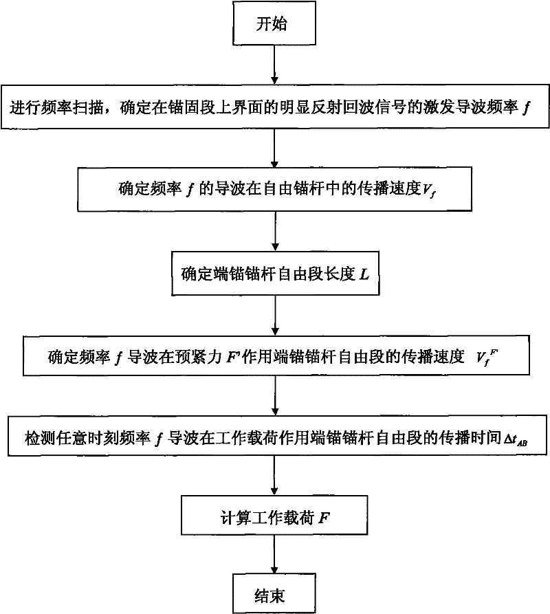
[0042] Using a guided wave with a frequency of 50kHz to detect a free bolt, the measured V f =5010.4m / s, according to step 3, the frequency of 50kHz guided wave is measured at the propagation time t=3.992e-4s of the free section of the end anchor and bolt without working load, and then the length of the free section of the end anchor and bolt is determined L= 1m. Apply a preloading force F'=40kN to the anchorage bolt to be tested, and the propagation time Δt of the guided wave at the free section of the anchorage bolt at the end of the preloading force AB '=3.995e-4s, then the propagation velocity V of the guided wave at the free section of the anchor bolt at the end of the pretightening force is obtained by step 4 f F '=5008.8m / s. Measure the time Δt of the guided wave propagating in the free section of the anchor bolt under the action of the working load F AB =4.001e-4, the working load F=100.628kN is calculated from step five, and the actual value of the working load is ...

Embodiment 2

[0044] Using a guided wave with a frequency of 60kHz to detect a free bolt, the measured V f =4936m / s, according to step 3, the propagation time t=4.051e-4s of the guided wave with a frequency of 60kHz in the free section of the end anchor bolt without working load is determined, and then the length of the free section of the end anchor bolt L=1m is determined . Apply a preloading force F'=40kN to the anchorage bolt to be tested, and the propagation time Δt of the guided wave at the free section of the anchorage bolt at the end of the preloading force AB '=4.055e-4s, then the propagation velocity V of the guided wave at the free section of the anchor bolt at the end of the pretightening force is obtained by step 4 f F '=4934.4m / s. Measure the time Δt of the guided wave propagating in the free section of the anchor bolt under the action of the working load F AB=4.0615e-4s, the working load F=102.2kN is obtained from step 5, and the actual value of the working load is 100kN,...


PUM

PropertyMeasurementUnit
radiusaaaaaaaaaa
elastic modulusaaaaaaaaaa

Abstract

The invention relates to a method for non-destructive testing of the working load of a bolt by using a low-frequency guided wave, which can detect the change of the working load of the anchored bolt on site, and belongs to the field of non-destructive testing. This method firstly determines the propagation velocity of the guided wave in the free bolt and the length of the free section of the end anchor bolt, then determines the propagation velocity of the guided wave in the free section of the end anchor under the action of the pretightening force, and finally establishes the relationship between the working load and the guided wave. The relationship curve of the wave propagation time in the free section of the end anchor bolt. On this basis, the size of the working load can be determined by detecting the reflected echo of the guided wave on the upper interface of the end anchor bolt anchorage section and the propagation time in the free section. . The method can detect the working load of the anchor bolt, and the reliability is increased, and the method is simple, the operability is strong, and it is easy to monitor in real time.

Description

technical field [0001] The invention relates to a method for non-destructive detection of the working load of a bolt by using guided waves, which can detect the working load of the anchored bolt on site, and belongs to the field of non-destructive detection. Background technique [0002] With the development of the mining industry, the stability of underground structures has increasingly attracted people's attention. The research on the stability detection of roadway surrounding rock has developed to a new stage, and there are many mature technologies, such as roadway surface convergence displacement , deep base point displacement measurement, surrounding rock loose circle theory and detection, these technologies have been widely used in the stability control of coal mine roadway surrounding rock. However, these studies on the stability of the surrounding rock of the roadway structure all use the statics in solid mechanics as the main method, and the deformation of the surro...

Claims


Application Information

Patent Timeline
Patent Type & Authority Patents(China)
IPC IPC(8): G01L1/25
Inventor 王成何文宁建国唐永刚
Owner BEIJING INSTITUTE OF TECHNOLOGYGY
Why Eureka
Try Eureka